Learn about incredibly important solder pads. You’ll also have a closer look to some detailed information on how to use them, as well as anything you need to know on how they can be repaired with an advanced solder pad repair kit. This guide which covers all the aspects of soldering techniques PCBs solder pads will help you to master this procedure.
What are PCB Solder Pads?
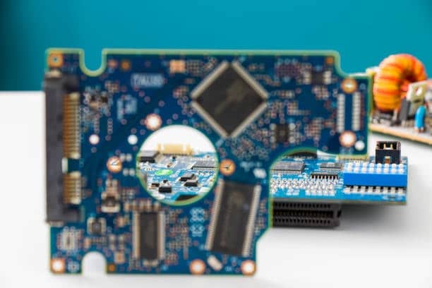
Solder pad is a part of solder planning, located on the printed circuit board (PCB), that is designed to attach electronic components by soldering a wire. The like structures are usually of metal layer on the boards where contacts links leads or solder joints to the printed conductive tracks of the board, thus they are connected electrically. These pads perform crucial function of ensuring a safe and strong connections between different electronic components as well as serve as a base for assembly of the PCB printed circuits.
What are the types of PCB Solder Pads?
Through-Hole Pads:
These holes in pads are developed for the directing the lead through your circuit board from connecting the printed components through soldered sides gives more components a stable mechanical backing.
Surface Mount Pads:
These lands are present on the top of PCB making solder for Surface Mounting smaller Components unlike through hole pads while their placement only offers space-saving but not automated assembling.
Thermal Pads:
Since there are areas on different components were heat can quickly collect, these pads must be proficient in wicking away the heat to help with the thermal and mechanical stresses as well as to protect and avoid further damage to pcb pads due to overheating.
Solder Mask Defined Pads (SMD Pads):
These includes the solder pads that is laying solder mask over the surface mount PCB leaving openings in exact area where the solder pads are require. It makes itself the accuracy place for soldering and transfers of solder bridging from pads.
Plated Through-Hole Pads:
With plated holes, interconnectivity between different complex multi layer boards and components can be provided through electrical connection between the multiple layers of the PCB pad.
In general, there are certain types of pads, and each has unique features, which are modelling design needs and the production process.
What are the common shapes of PCB Pads?
The common shapes of PCB pad includes:
- Rectangular Pads: Common and simple, this also implies having oblique edges for soldering most of the components.
- Round Pads: Resistors and capacitors can be jointed with components that have juxtaposed fusing levels as well as stress points.
- Square Pads: Like the Full pads but with equal-sized sides that shape it for symmetry and other component positions in some cases.
- Oval Pads: Utilized for irregular lead parts, providing the function of bending to these parts, even a long lead orientation is not an obstacle.
- Custom Pads: Custom-made to specific parts needs, including those that are of the level higher than initially seen, with lead modification mechanisms or those containing specially made thermogenerator instead of inductor.
What are the PCB Solder Pads Design Layout Guidelines?
PCB Solder pad design layout guidelines include:
- Pad Size and Shape: To avoid any difficulties with the component lead fusing, make sure that the sizing and shape of the pads complements the component, including parameters like the diameter of the lead and the pitch.
- Clearance: Ensure that pads clear each other well to limit the chance of solder bridges during assembly.
- Orientation: Line pads with components orientation in mind, such that pads and soldering points, as well as component lead, are in an aligned position.
- Thermal Considerations: Develop a PCB pad which has a larger area for space taking components, for example, the usage of the larger pads for the higher key positions allowing CPU cooling.
- Solder Mask: Apply solder mask to form pad patterns and prevent solder bridging, which is a critical requirement for accurate connection.
- Annular Rings: The annular ring width should be adequate enough to avoid through-hole pads breakdown, for the sake of proper solder joints reliability.
- Placement: Cunningly place pcb pads so as to maximize circuit board layout and routing performance and minimize interference. Be sure to do signal integrity and interference evaluation on the side.
- Trace Width: Conduct in accordance with pad regulations for simple soldering and current transport.
- Testing: Include testing points or PCB pads that are reachable and this helps in debugging and testing of a board.
- Compliance: Use the same industry standards and manufacturer recommendations as a guideline in designing solder pads to achieve good performances and high quality.
Constraining these rules will maximize the quality of the finished product, allow for smaller space, faster assembly, higher reliability, and good performance.
What are the Common Causes of Solder Pad Damage?
Common causes of solder pad damage on a PCB include:
- Overheating: Heating beyond necessary temperature can be damaged pads, becoming delamination and lifting of pad surfaces.
- Mechanical Stress: Unprofessionally seating, tweaking and repair can lead to uneven padding lifting and tearing in those moments pcs are flexed or vice-versed.
- Corrosion: Applying a surface to a repair pad in a humid or a corrosive atmosphere may contribute to a corrosion of this fixed pad resulting in a diminution of it compacity.
- Incorrect Soldering Techniques: The painting of too much solder or the use of poor flux can cause solder bridges, pad erosion or lifted overaged pads.
- Component Removal: Putting at the components out of the wrong place: through-hole components, in particular, can cause the pad to be broken if too much force is used.
- Chemical Contamination: The adhesion between the flux residues and the cleaning chemicals, and other chemicals can decrease pad surface life span with time.
- Poor PCB Manufacturing Quality: The process of making boards with gaps and other defects, for example, uneven coating or complete wardrobe shortage may jeopardize the strength and reliability of pads.
- Environmental Factors: The durability of liners is granted following the long-term exposure to the extreme temperatures, humidity or chemicals.
- Electrostatic Discharge (ESD): When haphazard ESD events occur, it leads to slight surface damage on the pads which is further escalated if any nearby sensitive components are involved.
- Improper PCB Handling: The problem of PCBs abuses can arise during the process of assembly, testing or transportation and then the solder pads will be definitely damaged.
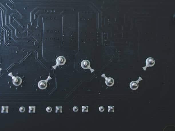
How to Fix Broken or Damaged Solder Pads?
Fixing bent component pins or replacing torn solder pads on a circuit board is a hard job, but some pin bends or connection tares can still be repaired with a critical eye and the right tools. Here’s a general guide on how to fix broken or damaged solder pads:
- Assessment: It is advisable to first evaluate the extent of the damage. Decide whether pad is partly lifted, fully dismounted or just damaged but still connected to the board. Assess align traces or structures nearby.
- Clean the Area: Apply isopropyl alcohol with a fresh tow while softly cleaning the damaged pad. In this case, make sure you are using a lint-free and clean cloth. To make sure that there is no debris, flux residue, bent pins, or contaminants that will affect the repair process what so ever.
- Pad Reattachment (Partial Lift):
- If the pad is almost lifted and is still connected to the pad, hold on gently to the copper trace underneath and lift the pad further to completely expose the copper trace.
- Raise the copper trace that is outside to an abrasive pad or fiberglass brush to eliminate the oxidation or dust.
- By using component leads or flux in the is cleaned area, better flow and adhesion of solder can be achieved.
- Here you should employ a fusing iron having a fine tip to fuse down the lifted pad that was previously on the exposed copper trace. Feeding connection in between both the pad and the trace and making sure it’s well bonded.
- Finish by reflowing the joint, review the result and verify that there is no bridging or cold joints.
- Pad Replacement (Completely Detached):
- If the pad is torn off really badly, you may have to buy a new pad to replace it.
- As stated in the previous paragraph, clean up for the area surrounding the pad is also important.
- Have a backup pad that has a segment of copper foil cut by you or use a replacement pad.
- Subject the area of the pad to the effect of flux.
- Use the connecting iron to steadily fuse on the new pad onto the trace of exposed copper for quality connection.
- Review the repair for good alignment and fusing practice.
- Trace Repair (Damaged Trace):
- If the copper trace linked to the pad is faulty, you’ll be required to fix or change the broken part of the copper trace.
- The hobby knife or fiberglass brush can be utilized with care to remove any parts which are stained, twisted or worn out from the trace.
- First of all, clean the part well and apply flux.
- Connect a small piece of copper wire there or paint conductive ink or paint to fill the gap up.
- Make certain that the fixed circuit is secured against interferences.
- Final Inspection: After repairing it, it is vital to track the alignment very carefully to avoid any further problems along with proper fusing and electrical continuity inspection. The repaired pad or traced need to be checked and track the connection is okay.
- Preventive Measures: Think applying coating like epoxy or conformal after the repairing for getting the better mechanical strength to the area as well as further damage protection.
In some cases, the damage may be more complex or the skills to repair it be out of your scope. In such instances, it is helpful to have a specialist PCB repair company or substitute the damaged PCB for a new one.
What are the advantages of using solder mask defined pads in PCB fabrication?
Using solder mask defined pads or (SMD) pads in PCB fabrication brings several advantages compared to nsmd pads:
- Prevents Solder Bridges: SMD pads pitch a qualified opening, a less possibility of fusing breach between adjacent pads during assembly.
- Ensures Accurate Soldering: These pads are specific ink locations where solder is placed bringing about the precision transfer and saving on negligible faults such as shorts and weak connection joints.
- Boosts PCB Reliability: Important to provide a quality connection achievement and as a result, the board has a reliable performance with consistent results.
- Saves Space: Pad areas locations are defined, components are allowed to be adjacent to each other, and thereby more space on PCB is optimized by placing components without compromising reliability.
- Promotes Consistent Joints: A factor that helps to create a distribution of connection joints which in turn ensures better electrical connection and entire performance.
- Facilitates Inspection: Distinct areas of limit pads make connection joint inspection easier and they contribute to implementing quality control measures to ensure process consistency during manufacturing.
- Reduces Costs: As re-work shortage implies lowering the cost of production on the mid-term.
- Compatible with Automation: SMD pads are designed for use with automated machines processes, thus being appropriate for high volume productions where efficiency is required.
In essence, SMD pads help in quickened soldering, enhance reliability , save space and also contribute in cost saving printed circuit board production.
What are the key considerations for designing surface mount pads to ensure proper soldering and component placement?
When designing surface mount pads for proper connection and component position on a circuit board, there are several key considerations to keep in mind:
- Pad Size and Shape: Verify that the outline and shape of pads are compliant with the component footprint characteristics and the lead configuration. Correctly adjusted pads make the component fusing work reliable and prevent solder alloy bridges.
- Pad Placement: Set up the pads according to the element’s datasheet and footprint specification criteria. Appropriate bonding involves good component positionwhich shall prevent errors in position.
- Solder Mask Definition: Define pad areas by connection masks, only the right metal would be exposed to fusing. This way, fusing doesn’t move from where it is supposed to and the possibility of bonding bridges sinking between pads is reduced.
- Pad Spacing: Make sure that there is enough space between the pads to avoid forming of connection bridges and improve fusing performance. The leader pitch must be accommodated and connection should flow in straight pathway.
- Thermal Considerations: Design thermal pads to accommodate the requirements such as those connection points that have been comprised of heat generation components. Adequate size and position of the connection points promote the heat across the element of the printed board and thus allow avoiding connection joint failure within the result of thermal stress.
- Pad Surface Finish: Select a suitable surface mount finish for pads, for example, HASL (Hot Air Solder Leveling), ENIG (Electroless Nickel Immersion Gold) or OSP (Organic Solderability Preservative), to achieve good solderability and long-term reliably.
- Stencil Design: Design joining paste stencils with apertures that are of the right size and shape and correspond to pads to enable accurate joining paste dispensing during assembly. Proper stencil design is among the most crucial things for a smooth connection joints.
- Assembly Process Compatibility: Look at the assembly process and select the pad design ( able / compatible) with the automated assembly equipment. The pads which are well designed assure the proper joining with less chances of failure during the automated pads.
By considering every aspect of surface mount pads design from soldering and components position to the manufacturing efficiency during the PCB pads designing phase, we can end up with the optimal design of surface pads.
What factors influence the size and shape of solder mask apertures in PCB fabrication?
The solder mask apertures diameter size and shape are related to several aspects in the designing of printed circuit boards fabrication. Firstly, they conduct footprint of the components soldered, where dimensions and position for the pads of soldering components define the apertures’ shape and position. The aperture and pads must be lined up correctly to not affect circuit boards and ensure right base for assemblage.
Furthermore, the integrity of spaces between through-hole pads require attention as well as they enable connection bridges to be avoided during manufacturing. Therefore, the sizes of the apertures should be the same or almost the same as the spatial spacing demand. The selected connecting process, reflow bonding or wave bonding method, plays role in defining aperture design, which may not involve joining application throughout its area, but reduce the formation of solder mask residue.
Additionally, solder mask thickness generally comes in at the cost of aperture size, thus thicker layers may require opening of larger aperture holes to account for adequate pad exposure. Considering the process of manufacturing tolerances, as well as electrical clearance around the conductive traces and pads, and also thinking about the ready use of assembly equipment are the most significant questions here.
Conclusion:
Solder pads are crucial elements in circuit board design either acting as the connecting points or connection points to appends electrical components on PCB. They can be in different types, such as rectangular, circular or square which are made to accommodate different component layouts as a necessity. Quality layout in design is very important to achieve the strength of connections and secure stability of the electrical as well as counter aspects on mechanical stresses.
Indicators include dimensions, spacing, and heat aspects of installations. Defects on solder pads can be caused be overheating or stress during assembly and corrosion, and care must be taken when repairing these errors. With SMD pads soldered mask allocation given, you receive high density, less connection mispositioning and higher complex coating precision. To sum up, fusing pads have a great deal of significance in the workings of the electronic components.