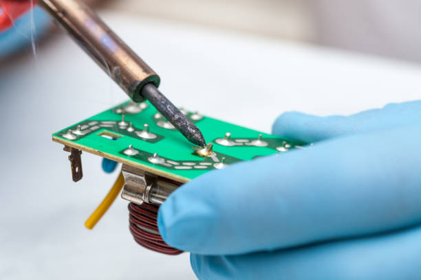
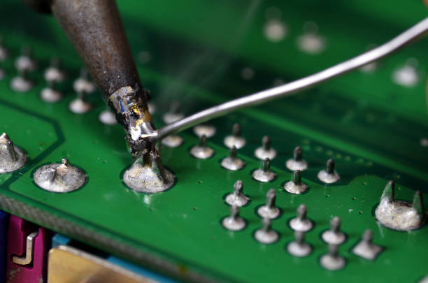
Soldering is essential for passing pieces of electronic equipment into non-hostile gear on printed circuit boards (PCBs). A proper and properly soldered joint and connection is one that ensures both good physical and electrical cohesion. Nevertheless, the most frequent cause of lacking bonds is that the joints are formed incorrectly, known as the cold soldering process. Identifying the root causes and gravity and developing potential options for cold solder joints is indispensable in the design of quality electronic devices.
What are cold-solder joints?
On the other hand, a cold solder joint, which is the same as a disturbed joint, may occur if the solder does not melt and bond the joint properly, leaving an uneven and untrustworthy gap instead of a smooth, shiny joint.
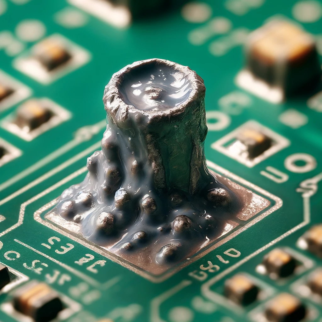
On the contrary, the ideal solder joint will look dull, grainy, or cracked. You might be able to notice cold solder joints, and they are the connection points that are not durable and known to cause intermittent or complete connection failure.
Cold Solder Joint and Why it Should Be Avoided
A solder joint is cold when the soldering element does not melt and flow correctly around the parts. This can lead to a break in the line or a bad electrical contact. Here are some key points about cold-soldered joints and why they should be avoided:
Causes of Cold Solder Joints

- Insufficient Heat: If the soldering iron is hot enough and the components are heated well enough, the thermo effect will not be complete, and the solder will not melt down properly.
- Improper Technique: The rate at which they move the soldering iron or the way in which they apply the solder can create incomplete melting and reduced fluidity.
- Contaminated Surfaces: Dully, oil, or oxidation on the surfaces you want to solder will prevent proper wetting and bonding of the solder.
Why Cold Solder Joints Should Be Avoided
Cold-soldered joints should be avoided because:
- Weak Connection: They produce the joining of two wires that are poor electrical.
- Increased Resistance: They will have higher electric resistance.
- Mechanical Fragility: Even the smallest trifle hinders their operation.
- Short Circuits: They cause damage to the circuitry.
- Reliability Issues: They violate the adherence of devices to specifications.
Consequences of Cold Solder Joints
The soldered joints, where one metal is frozen while the solder mask the other is very hot, can have a substantial influence on how well the device is working and how reliable it is.
- Intermittent Connections: Cold bonds often offer a poor electrical connection that can make switch on or switch off operations rather fragile, especially under mechanical stress or heat and cold cycles.
- Component Damage:An inadequately finished soldering job can result in heat during use, which might further damage the parts.
- Reduced Lifespan: For electronic devices such as gadgets with cold solder joints, the mean time to failure between the two components will be less than the one with good joints.
- Increased Repair Costs: The cold solder points’ detection and repair is a mentally and financially taxing process when there are lots of electronic devices involved, in particular in the case of the complexity of the devices.
Solutions for Cold Solder Joints
The prevention of cold bad solder joints that, along with the correct temperature and soldering process, contributes to the correction of cold solder joint problems.
- Proper Heating: Make sure that the soldering iron is not set beyond the specified temperature and that its soldering iron tip gets hot enough to heat both the component lead and the pad.
- Good Soldering Technique: Keep the soldering joint and components still when the soldering process is done.
- Clean Surfaces: All the leads as well as the surface mount PCB pad should be cleaned with some isopropyl alcohol or a specific cleaning agent before beginning the soldering process.
- Use Quality Solder: Invest in an excellent-quality bare solder lead with a flux core to increase the efficiency of the flow and join.
- Regular Equipment Maintenance: Routinely check and maintain the equipment you are going to solder to ensure that it is working properly.
- Reflowing:Besides, if a collapse of the graser joint takes place, in many cases it can be triggered by soldering it again. This is performed by raising the joint temperature to 400 °F, re-melting the solder one more time, and allowing it to solidify.
Identification of Cold Solder Joint
Detecting inherently brittle cold solder joints increase which is the main measure that has to be taken to avoid electronic board reliability degradation. Here are some key points to help you identify cold solder joints with the latest information:
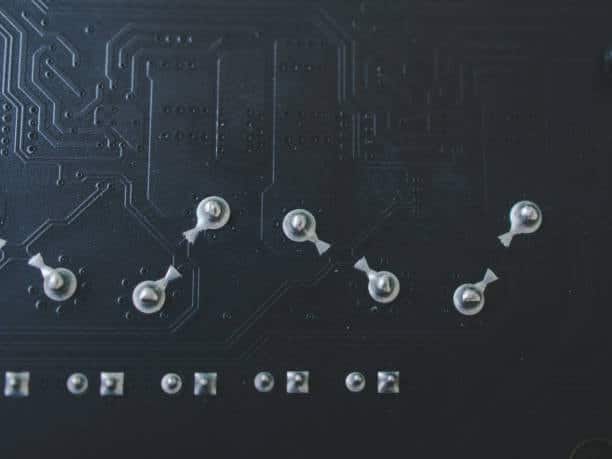
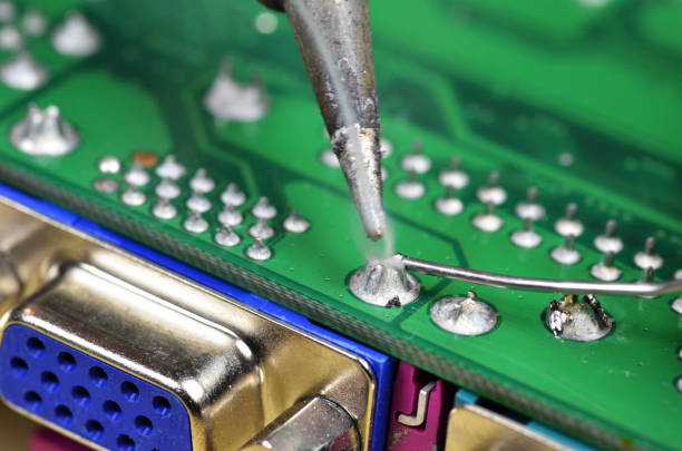
Visual Inspection
- Dull or Matte Finish: As it happens, the bright and smooth appearance of a rightly forged joint is unmatched by the dull or softly shiny finish of a cold solder; sometimes there is a grainy surface.
- Irregular Shape: A bad solder is often cauliflower-shaped and hence without smooth corners. This tells us that the solder rice should not flow freely.
- Lack of Wetting: Applying the sealant may not have been done by wetting or even tailing, so the joint does not appear to have been uniform around the pad and pin lead.
- Visible Cracks: In some situations, you may notice a trace of solder cracks or even solder joint breakages.
Physical Inspection

- Loose Connections: The connection may be slack, or maybe there’s some movement. Thus, the conductor or the solder wire should be carefully stretched to determine if the connection is slack or if there is any movement.
- Flex Test: But moving slowed down, make sure the joint is tight; the chip has no breakpoints.
Testing and Measurement
- Continuity Test: Evaluate the conductivity using a multimeter. In the case of a quick cold-soldered joint, the joint can either be an open circuit or a short circuit, which must be considered.
- Resistance Measurement: Measure the conservation over the exocage to determine which joint needs to be fixed. The one who is seeking side this time can be a plain joint changing on a cold solder joint.
Thermal Inspection
- Thermal Imaging: A thermal camera is an efficient instrument to see cold solder joints. This is because it shows a temperature difference in the solder joints compared to the soldering points.
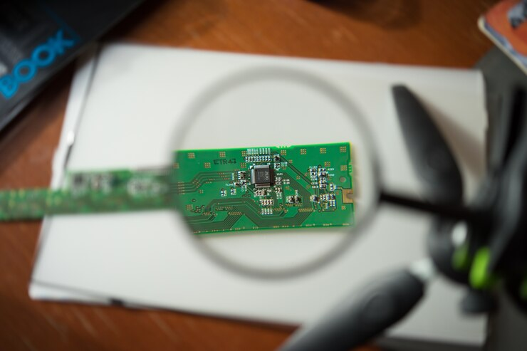
Advanced Techniques
- X-ray Inspection: In cases of critical applications or complicated ones, X-ray visualization may allow examining the solder joint and identifying a lack of connective bonding or voids.
- Microscopic Examination: Through the microscope, one can detail areas that are not visible to the naked eye, including micro-cracks or poorly bonded intermetals.
Prevention and Remediation
- In order to prevent cold joints, ensure good soldering technique, heating adequately, and using appropriate solder masks and flux.
- In this situation, the weak soldering joints must be fixed by securely melting the solder by heating and resoldering the junction. Thus, it will provide a strong, solid, and reliable connection.
Through this careful observation more solder, and the application of appropriate assessment methods, you may successfully locate and fix the common problem of cold solder joints in your electronic projects.
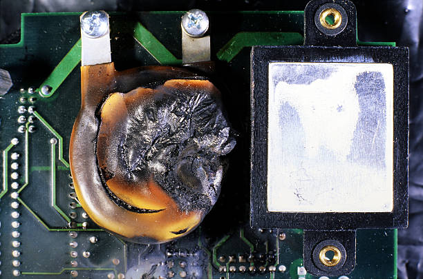
Effects of Cold Solder Joint
While cold solder joints might be innocuous at first sight, below deck, there are some negative effects on electronic circuits. Here are some of the latest insights into the effects of cold solder melts over-soldered joints:
- Poor Electrical Conductivity: At high temperatures, solder joints show resistance because it is difficult for electrons to cross the big metal atom assemblages. This can lead to voltage dropouts, power loss, performance inefficiency of the electronic appliances, and so on.
- Intermittent Connections: These joints provide intermittent connections, and the devices can crash occasionally if these mechanical connections aren’t well-engineered. This cyclic behavior, which is hard to detect and is associated with breakdowns in the operation of such a device, is one of the factors that makes this unit an unreliable source of power.
- Increased Risk of Failure: Solder joints getting colder too often may be broken as a result of their parafragility. Their compressive strength is very low; therefore, they can be easily fractured or cracked under sharply differentiated pressures, resulting in their circuit’s failure and the device as a whole.
- Overheating: Because of their higher resistance, cold solder joints can make the locations in the circuit get warm. Hence, this will tremendously increase the thermal restraints that the components exert, increasing the probability of failure.
- Signal Distortion: A cold or loose solder joint can permeate the electrical connection and degrade the electrical signals, resulting in signal distortion, noise, and signal degradation and affecting the overall device performance.
- Reduced Lifespan: When soldering, there is an increased level of failure and the possibility of causing damage to other nearby pieces of a circuit due to the presence of cold joints that will ultimately cut the electronic device’s lifespan short.
- Increased Maintenance and Repair Costs: It may call for more repairs and maintenance cycles, which leads to additional operational costs and slows down the production schedule.
In mitigating these effects, it is paramount to make sure that all solder joints are well formed in the manufacturing process and to fix the cold solder joints that have been formed as issues in quality control and that could appear during the lifetime of the device. Just heat the endpoint of stray solder on the iron and carefully trim the excess solder, or try using a solder sucker for this purpose.
Prevention of Cold Solder Joint
By preventing the cold solder joint:
- Proper Heat Application: Make sure the soldering will be applied to the joint when the soldering iron is heated to the appropriate temperature. Just as if it does for the punk, it should heat both component and junk.
- Sufficient Flux: Choose an optimal amount of flux to help clean the surfaces and provide better solder flow which reduce the possibility of oxidation that appear as cold joints.
- Adequate Solder: When necessary, apply a reasonable amount of solder that would be the same as the joint area you want to cover without exceeding the extent of the overflow.
- Correct Soldering Iron Tip: Adopt a sizeable tip type varrying in components and pads sizes so to achieve efficient heat transmission.
- Stable Components: Ensure that all pieces stay at their respective places during soldering in order to avoid disturbance that may lead to inadequacy in the formation of joints.
Soldering Problems
Soldering issues can cause the quality and reliability of a circuit to largely depend on the degree of accuracy of the soldering. Here are some common soldering problems and their causes:
- Cold Solder Joint: This effect takes place in cases where the solder doesn’t melt apart, which results in an incompetent and poor connection. The reasons behind it may be unsuitable heat, a dirty surface, or not using the right heating method.
- Dry Joint: As a dry joint resembles a cold joint or cold solder joint, we can observe that it also appears dull and uneven, sometimes with a cracked surface. It happens because of the insufficient volume of heat or the lack of motion of the portion such as joints during the soldering.
- Excess Solder: The excess solder may result in the circuit malfunctioning or might cause difficulties in tracing. It is commonly attributed to soldering for too long or using too much solder as the reasons for this issue.
- Insufficient Solder: An improperly formed joint with too little solder becomes weak and may break when subjected to excessive force. It usually happens with a lack of solder being applied or the soldering iron being moved too early.
- Solder Bridges: This happens as the solder accidentally attaches both pads or leads that are too close together, which can result in a short circuit. It can start with the use of too much solder or the soldering iron’s accidental slip onto different pads on the solder bridge.
- Overheated Components: Extra heat exceeding the predefined limits can destroy delicate elements or even a sensitive circuit board. It is hypothesized that in this case, the heat is applied for a long time and/or the soldering iron is too hot.
- Cold Spots: This is the type of small error that manifests itself when the solder does not stick to the given area of the board, and this appears in the form of a dark spot within the joint. The factors that lead to this wearing off are surfaces that are not well handled, which block the solder flows of electrons, or a poor connection between iron and steel.
- Tombstoning: This is a defect that happens when a chip mostly alters its shape off the board during soldering, resembling a tombstone. This defect can be found rather frequently in connectors and is usually caused by unbalanced heating or soldering one side of the component before the other.
The above problems could be avoided in instances where the correct temperature was the burnt flux was used to solder, applying heat and solder was done properly, surfaces were kept clean, and the flux and solder were the correct amount.
The Ideal Surface Mount Solder Joint
An ideal surface-mount solder joint should have the following characteristics:
- Wetting: The solder plating is expected to uniformly over the pad and component lead to form a uniform, concave fillet ultimately.
- Shape: There should be a small convex or hollow shape, which means the solder temporarily expands after the solder joint is completed and then shrinks after the part is cooled, which is a sign of good wetting and an adequate volume of solder.
- Size: The solder should be longer than the pad itself but should not exceed preventing the pad from being covered completely and with not enough spillover.
- Brightness: The pan and its inner walls should be very shiny, which is a sign of proper roasting and cooling.
- No Defects: The indication of a good soldering overheated joint should be clear, with no cracks or voids, no filings of solder, and no excess flux residue.
Conclusion
A cold solder joint is a usual but preventable problem in soldering and is usually why you have a popping or bubbling sound. A solder-starved joint simply does not have enough solder. It has a detrimental effect on the power transfer and can spoil the contact, thus making the device useless. If you know the causes of cold solder joints and implement the correct soldering process, you will be able to ensure the dependability and long-term operation of your electronic equipment.