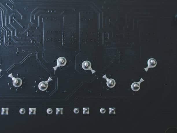
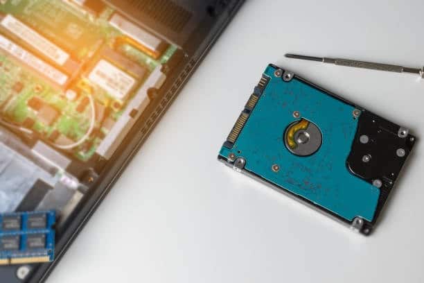
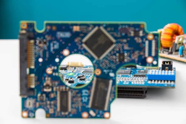
PCB material selection is very important for the performance and reliability of electronic devices. With this guide, you’ll be able to determine exactly which type of PCB material your design requires. The choice of PCB material is important to the performance and reliability of your printed circuit boards. This complete guide will arm you with all the information to assist in making an appropriate decision about what PCB material is best-suited for your project. We’ll review factors that affect a choice in substrate layer board, then examine some common insulators and their respective applications.
What Is a Printed Circuit Board?
Printed circuit boards (PCB) are an essential part of electronic devices, providing a plane for various kinds of electric elements. Its construction is of a non-conductive substrate such as this fiberglass-reinforced epoxy with thin layers (usually copper) applied to give the electrical signal pathways. These paths, known as traces, form a conduit for the flow of electricity.
Resistors, capacitors and integrated circuits are conveniently mounted on the PCB as electronic components; soldering them together gives a working electrical system. It provides a small, neat and reliable means of connecting components together in everything from smartphones to computers. PCBs are at the center stage for modern electronics nowadays.
What are PCB Materials?
PCB materials are defined as the substances used to build printed circuit boards (PCBs). These materials include:
1. Substrate Materials
Made mostly of fiberglass-reinforced epoxy, the substrate gives structure to the PCB.
2. Conductive Layers (Copper)
Conductive paths for electricity: Copper layers are applied to the substrate.
3. Advanced Materials
Depending on specific application requirements, PCBs may contain high-performance materials such as radio frequency (RF) laminates used in many RF applications or flexible substrates for making a flexible PC.
The choice of PCB materials determines the board’s performance characteristics, such as signal integrity and thermal management. As a result, designers choose materials according to the nature of their intended electronic applications for maximum efficiency and dependability.
What Are the Different Types of Material Used for PCB?
Printed circuit boards (PCBs) are built with different materials, each offering special qualities to suit the requirements of differing applications. Some common types of PCB materials include:
FR-4
Fiberglass-epoxy A commonly used flame retardant material with good electrical insulation.
FR-2
This is the poorest performing of all substrate materials. FR-2 is short for flame retardant level 2. It comprises phenolic material. In addition, FR-2 is widely utilized in cheap electronic consumer goods like small low cost radios.
FR-1
FR-1 is perfect for single-sided PCBs. It is a paper-based fire retardant level 1 material. It is the identical properties that make it similar to FR-2. Yet FR-1 has a higher temperature value.
High-Frequency Laminates
Made specifically for RF and microwave applications, these materials have low signal loss at higher frequencies.
Flex Materials
Flexible PCB materials based on polyimide, suitable for applications with bending or small form factors.
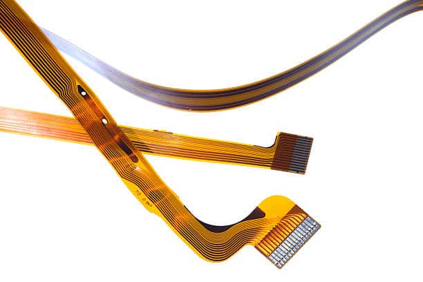
Metal Core PCBs (MCPCB)
Also common in LED applications, are those with metal cores–either aluminum or copper, for better thermal conductivity.
Rogers Materials
RF and microwave circuits use high-performance laminates.
PCB material is decided by several factors, including its application, operating environment and conditions (temperature range), signal frequency considerations. as well as thermal aspects. According to such factors, designers choose materials for the electronic device in order to reach good performance and reliability.
Other PCB Substrate Material Types of pcb materials
Apart from the conventional FR-4, high frequency laminates and flex materials as well as metal core PCBs and Rogers materials used in printed circuit boards (PCB), there are other various substrate materials for different application needs. Some notable types include:
- Polyimide (PI): Because polyimide has excellent high-temperature resistance, it is often used in flexible PCBs. It’s also a good choice for applications where the board must flex or conform to some sort of shape.
- Teflon (PTFE): Teflon-based materials ensure excellent electrical performance, low signal loss and are thus often employed in high frequency applications.
- Ceramic: In applications that require both high thermal conductivity and the ability to endure a harsh environment, ceramic substrates are used.
- Aluminum: Aluminum-based PCBs or metal core PCBs are used when rapid heat dissipation is a key consideration, and therefore suited for applications such as LED lighting.
- Nelco: A high-speed digital laminate designed with low signal loss and excellent electrical performance.
The decision of what PCB substrate material to use will take into account such things electrical performance, thermal characteristics, flexibility and the particular needs for which it is intended. The substrate material is selected by the designers to achieve an optimum combination of performance and reliability for the finished electronic device.
What PCBs exist and what are they made from?
PCBs come in different shapes, materials and are designed for various applications. Common types of PCBs include:
Single-Layer PCBs
In general, FR-4 is used as the single layer of substrate material. Conductive traces are laid out on one side only. Common in simpler electronic devices.
Double-Layer PCBs
The two layers of substrate material are separated by a layer of insulation. There are conductive traces on both sides for more complicated circuitry.
Multilayer PCBs
Several layers of substrate with conductive tracks, for greater complexity and connection. These advanced materials could include high-frequency laminates or flexible substrates.
Rigid PCBs
Have a firm, rigid structure and are often employed in old electronic equipment.
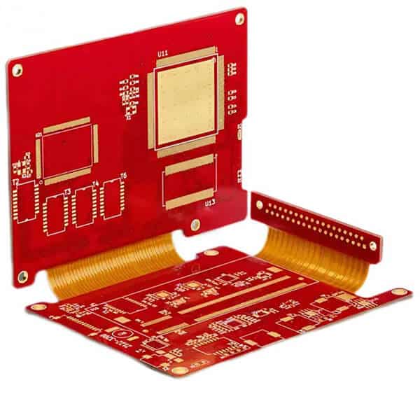
Flexible PCBs (FPCBs)
Employ flexible substrate materials, such as polyimide. These can be bent or conformed to a particular shape. Suitable for applications with space restrictions and moving designs.
Rigid-Flex PCBs
Combine stiff and elastic PCB elements on one board, providing both structure stability as well as flexibility.
Substrate materials like fiberglass-epoxy composite FR-4 are the chief components of PCBs. Other materials such as copper for conductive traces and various laminates are used to create the layers, so that electrical connections can be made. Depending on the requirements of a given electronics application and what performance characteristics are needed, one chooses for his PCB particular types and materials.
Factors to Consider When Choosing PCB Materials
When choosing plastics for printed circuit boards (PCBs), there are various things that need to be looked at in order to achieve the best performance and maximum reliability. Some key considerations include:
Electrical Properties
When we know it, the electrical properties have dielectric consumer electronics, which are called a dissipate heat factor as well as the insulating material resistance, which affect the electrical components performances like signal integrity and transmission.
Thermal Properties
These two parameters are used to improve thermal management of PCBs, and determine the reliability for applications that require heat dissipation.
Mechanical Strength
The mechanical properties of the material, such as tensile strength and flexural modulus determine PCB ’ s structural toughness. This is particularly true of applications that are subjected to stresses from outside forces.
Chemical Resistance
This is especially important for applications that must endure difficult environmental conditions, so as to avoid degradation and ensure reliability over the long haul with high temperature resistance.
Cost
Actually, the material costs are a relatively large part of all that pcb making money. Performance requirements and costs must be balanced in PCB production.
Availability and Lead Times
Because the availability and lead times of materials affect production schedules, you should choose types of pcb materials shells which are widely available with reasonable delivery dates.
Manufacturability
Besides insulation resistance, material should be easy to fabricate and convenient for PCB manufacturing. It must also suit the requirements of soldering process in actual applications.
Application-Specific Requirements
Depending on the application, there may be special material requirements. For example, RF applications might require high-frequency laminates; space considerations may call for flexible substrate.
Common PCB Materials
Commonly used materials in the construction of printed circuit boards (PCBs) include:
- FR-4: An epoxy-based flame retardant with a fiberglass core. FR-4 is easy in use and low cost, electrically insulating and versatile.
- High-Frequency Laminates: Special materials for RF and microwave applications that have low signal loss at high frequency applications. For instance, materials from Rogers Corporation are examples because or either have high temperatures, high thermal stability, high dielectric constant, high speed digital circuits.
- Flex Materials: Flexible materials based on polyimide, excellent choice for applications where the flexible PCBs needs to flex or fit into a particular shape like rigid flex boards.
- Metal Core PCBs (MCPCB): Use a metal core, usually aluminum or copper for better heat conductivity. Commonly used in LED applications.
- Polyimide (PI): Because of its high-temperature resistance, polyimide is frequently used in flexible PCBs.
- Teflon (PTFE): Teflon-based materials have great electrical performance and low signal loss, so they are perfect for high frequency applications.
- Ceramic: Special applications requiring high thermal conductivity and resistant to harsh environmental conditions use ceramic substrates.
- Aluminum: A good heat conductor which is often used in PCBs as a metal core, especially for LED applications.
Electrical properties vary from one material to another, as do thermal expansion and mechanical. The choice is determined by the needs of a given electronic components application. These material properties are carefully considered by designers, so that the PCB fabrication can meet standards of performance and will perform over a long period in its intended environment to the popular pcb material.
WHY DO WE USE PRINTED CIRCUIT BOARDS?
Because of their many advantages, PCBs are essential for electronics. They enable the neat and orderly arrangement of electronic components in devices, freeing up precious space.

PCBs simplify assembly, making components’ placement and soldering especially accurate. This controlled manufacturing process assures that electrical connections are stable and reliable, enhancing overall system performance. PCBs enhance the stability of electronic devices by eliminating connection problems, providing customized products tailored to different applications and enabling mass production.
Moreover, PCBs make troubleshooting and repair easier–a low-cost answer for mass producing electronics products. In short, PCBs are a basic building block in modern electronics that improve efficiency and reliability as well as help scale-up integrated circuits.
WHAT ARE PCB LAYERS?
PCBs are composed of layers, which consist of individual sheets stacked together to make up a complete circuit board. Each layer has a specific function and contributes to the PCB’s functioning. The common layers in a multilayer PCB include:
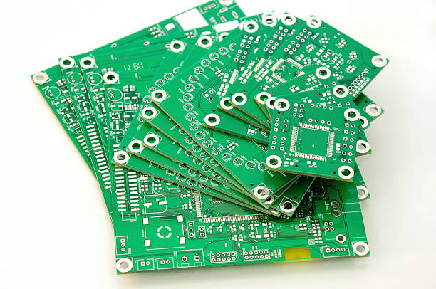
- Top Copper Layer: The traces that form the pathways for electrical signals are etched onto this surface of the PCB.
- Prepreg: Prepreg layers are composed of fiberglass saturated with resin. They lie between the copper layers and increase PCB thickness.
- Core Layer: The core layer is a central level that may have conductive stripes, and it can be made of FR-4 or some other substrate material.
- Bottom Copper Layer: Like the top layer, in turns out that the bottom copper layer also possesses traces on its underside.
These basic layers are stacked together in a multilayer PCB, and the whole structure is laminated to form an integrated circuit board. The number of layers in the PCB is determined by both the complexity and type of circuit board or printed circuit board pcb, as well as design requirements. Newer electronic devices make extensive use of multi layer PCBs to achieve smaller and more complicated circuits.
Types of Solder Mask Material
A protective layer over the copper traces on a printed circuit board (PCB) is applied using solder mask materials, preventing unintended solder bridges and proper soldering during assembly. Common types of solder mask materials include:
- Fine-resolution Liquid Photo imageable (LPI) Solder Mask for intricate designs;
- Dry Film Solder Mask, suitable for mass production having high definition.It can be applied to protect certain areas during PCB assembly and then peeled off later. Allows easy reworking or modifications after assembly.
- Thermal-Cure Solder Mask: Chemical resistant and durable.
- Peelable Solder Mask, which makes rework much easier after assembly.
- Cover lay, which is frequently applied in flexible PCB’s for protection without further solder masking. As a separate layer on PCB, laminated to protect certain areas. Often used in flexible PCBs and no solder mask application is needed.
- Epoxy liquid – This is a thermosetting epoxy, usually applied by silk screening. Because the epoxy liquid has low resolution and accuracy, it is not widely used the composite epoxy material, epoxy resin, epoxy resin binder and epoxy ink.
- Liquid photo imageable – Liquid photo imageable solder mask is particularly suitable for circuit boards with unusual topography. Different coating techniques are used to apply a UV curable ink. While this solder mask isn’t an even layer, it provides a better contact with the copper traces. In addition, it has a better coverage. It is especially suitable for circuit boards with very complex surface features.
There are various factors that affect the choice of solder mask materials, among which manufacturing processes and resolution requirements can be divided into categories. Special applications also have their own considerations.
Dielectric and Electrical Properties of PCB Materials
This is because the performance and functionality of electronic circuits are heavily influenced by such dielectric and electricla properties as those exhibited by PCB materials. Here are key considerations:
Dielectric Properties:
- Dielectric Constant (Dk): The ability of a material to store electrical energy in an electric field is known as this property. For good signal integrity, especially at high frequencies, a lower Dk is preferred.
- Dielectric Strength: It is the maximum electric field a material can endure without electrical breakdown. Preventing insulation failure requires that high dielectric strength exist.
- Dissipation Factor (Df): Df is the energy loss in a dielectric material. The lower Df is, the less signal loss and faster energy transmission.
- Insulation Resistance: This property designates the ability of insulating material to prevent electrical leakage. Impedance to unwanted current flow is mainly achieved through high insulation resistance.
Electrical Properties:
- Conductivity: The conductivity of a material for electricity. PCB substrates need low conductivity to prevent unwanted current paths.
- Impedance Control: For signal integrity, the impedance of transmission lines must be kept constant. Stable electrical characteristics in PCB materials make for good impedance control.
- Thermal Conductivity: Why is High Thermal Conductivity Important? Although a natural thermal property, high thermal conductivity can directly benefit electrical performance by dissipating excessive heat in power electronics applications.
- Relative Permittivity (εr): Like the dielectric constant, it affects a material’s capacitance. Maintaining a stable εr means electrically reliable PCB materials.
- Loss Tangent (tan δ): Represents the internal energy loss within dielectric material, and is used to describe dissipation factor (Df). Since loss is a problem, most prefer the low-loss tangent.
To ensure reliable, efficient electronic circuits it is necessary to select PCB materials with appropriate dielectric and electrical properties. Designers take these factors into account accordingly, based on the specific needs of an application. This is especially true for high-frequency and highspeed designs where signal integrity must be optimized.
Dielectric constant
Dk, or the dielectric constant of a material used in printed circuit boards (PCBs), is an especially important physical characteristic. It measures a material’s ability to hold electrical energy in an electric field. The higher the dielectric constant, the more electrical energy can be stored.
The dielectric constant is important for determining how fast electrical signals can pass through the substrate material in PCBs. For high-frequency applications, lower dielectric constants are preferable because they minimize signal delay and enhance signal integrity. Uniform and stable dielectric constants in materials enable the reliable operation of electronic circuits by allowing accurate transmission of signals, with low interference.
Volume resistivity
One of the most important electrical properties is volume resistivity, which describes how a material resists current flow through its bulk. In terms of ohm-centimeters (Ω·cm), volume resistivity symbolizes a material’s resistance to electrical conductance. The higher the volume resistivity, the better are a given material’s insulating properties. It prevents overcurrent flowing and keeps current from leaking where it is not wanted so that electrical isolation can be maintained between conductive elements in electronic circuits.
In particular, this property is very important in printed circuit boards (PCBs), so that incorrect signal paths are not created and different elements of the board do not interact with one another.
Because they reduce the risks of electric short circuiting and ensure signal stream integrity, materials with high volume resistivity are a key ingredient for reliable and efficient performance from electronic devices.
Surface resistivity
Surface resistivity is one of the basic electrical properties characterizing a material ‘s ability to prevent electricity from flowing over its surface. Surface resistivity, measured in ohms per square (Ω/sq), indicates how good a material is at resisting electrical conduction along its surface. In applications such as printed circuit boards (PCBs), where electrical isolation is a crucial consideration, this point must be taken into account.
The greater the surface resistivity, then the higher quality insulator it is and so there are fewer leakage currents. Leakage current weakens electronic circuits by introducing paths for unintended conduction that cause instability in operational voltage levels or create unnecessary side effects from heat developed through resistance of these accidental channels.
Electronic devices perform better and last longer because materials with clearly defined surface resistivity reproduces the desired electrical characteristics, prevents cross talk (where unwanted signal is coupled to a receiving circuit) or other interferences.
Dissipation factor
The dissipation factor, Df or tan δ (tan delta), is an important electrical characteristic that indicates how well dielectric material can store and release electric energy. It’s the ratio between that energy lost as heat and its stored in material during every cycle of an alternating current (AC).
Expressed as a dimensionless value the dissipation factor is an indicator of how well the dielectric can suppress loss and protect intact electrical signals. For printed circuit boards (PCBs), the lower a material’s dissipation factor, the better. A low-loss dielectric means less signal loss and more efficient transfer of energy. Electronic circuits are composed of various components, but makers take care to choose materials with low dissipation factors in order for them not only to boost performance, but also reliability through lower energy consumption and better signal transmission.
Thermal and Mechanical Properties of PCB Materials
A number of properties determine the reliability and performance characteristics of electronic devices, with thermal and mechanical being perhaps most important for printed circuit board (PCB) materials.
Thermal properties, such as thermal conductivity and coefficient of thermal expansion, determine how well a material can dissipate heat or expand (or contract) with changes in temperature. Thermal management must be efficient so that electronic components do not overheat.
The structural integrity of the material depends on its mechanical properties, such as tensile strength or flexural modulus. These characteristics are important for the mechanical stability of the PCB, allowing it to withstand factors like bending and vibration as well as external forces before compromising its functionality.
Glass transition temperature (Tg)
The glass transition temperature (Tg) is an important thermal property representing the point at which a disordered, amorphous solid begins to lose its rigid or ‘glassy’ condition and becomes more pliant-or what we would call rubbery. Among them, Tg for materials used in electronics and those incorporated into printed circuit boards (PCBs) is especially important. That’s the temperature at which its mechanical properties change.
Thermal conductive layers
Thermal conductive layers are often used in materials for printed circuit boards (PCBs) or electronic packaging, and fulfill an important heat dissipation function. The function of these layers is to gradually lose the heat away from electronics, thereby avoiding burning precious iron and protecting reliability.
Peel strength
Peel strength is defined as the force needed to separate or peel apart two bonded materials. With respect to printed circuit boards (PCBs), peel strength is important in measuring the adhesion between layers-for example, copper traces and substrate. A high peel strength means a strong bond, which maintains the integrity of PCB structure.
Peel strength must be adequate to prevent delamination, or the separation of layers (which can cause failures in both electrical and mechanical terms). During the PCB fabrication process, manufacturers carefully assess and manage peel strength to ensure that their product is reliable.
Moisture absorption
Moisture absorption is the ability of a material to take in and hold moisture from its surroundings. As far as the printed circuit board (PCB) is concerned, moisture absorption must be kept in mind. It can have a drastic impact on both the electrical and mechanical properties of PCBs. PCB materials absorb moisture, and changes in dielectric properties affect signal integrity.
What material is used to make a circuit?
PCBs are usually made from a substrate material known as FR-4 (Flame Retardant 4).
Composed of layers of woven fiberglass cloth impregnated with epoxy resin, FR-4 is a composite material. It is used for its superior electrical insulation and flame-retardant properties, as well as mechanical strength.
Printed circuit board assembly often use copper for conductive traces. This is applied to the substrate in such a way as to form the desired circuit pattern.
The combination of FR-4 and copper provides a reliable, durable base for electronic circuits in various applications.
What plastic are PCB boards made of?
But printed circuit boards (PCBs) are usually made of a composite material called FR-4, which is short for Flame Retardant 4. FR-4 is a woven fiberglass cloth epoxy laminate. The epoxy resin provides electrical insulation and mechanical strength, while the fiberglass adds strength to the material.
Since FR-4 has flame awareness, is a good dielectric material and cheaper than glass epoxy, it’s widely used in PCB manufacturing. The use of FR-4 combined with copper traces produces a stable foundation for electronic circuits in countless fields.
What is the best quality PCB material?
The choice for the best quality PCB material depends also on individual application requirements. For demanding applications, like aerospace or telecommunications that require high-quality PCBs, advanced materials such as high temperature FR-4 and specialized laminates designed for extreme frequencies are commonly used. Such materials should have low dissipation factor and high thermal conductivity to ensure signal integrity as well as efficient heat transfer.
In high-reliability applications, the choice of materials must ensure good mechanical performance as well. Typically these will be polyimide or PTFE which can withstand extreme environmental conditions. As a result, in the end it is these electrical, thermal and mechanical characteristics adjusted for suitability to various electronic devices or systems which determine the best quality PCB material.
Conclusion
In sum, one’s choice of PCB material must be well considered. Each factors counts toward the performance and reliability of electronic equipment as a whole. The dielectric properties–namely, the dielectric constant (Dk) and dissipation factor (Df)–affect directly electronic performance signaling. Thermal properties, including thermal conductivity and glass transition temperature (Tg) are very important because they determine whether heat dissipation is effective enough to avoid any thermally related breakdowns. The PCB’s structural integrity and manufacturability depend on such mechanical considerations as tensile strength, flexural modulus, and peel strength.
The long-term durability and stability of the PCB, especially in environments with adverse conditions are closely related to moisture absorption and chemical resistance. How thick the copper foil is affects its current-carrying ability and heat dissipating capabilities. There must be careful balancing of cost factors with performance requirements to make manufacturing economical.
A further consideration in the selection is industry-specific requirements. High frequency applications require specialized laminates and high reliability demands that materials must have superior mechanical and thermal properties. Regulatory compliance, such as adherence to the standards chartered by RoHS (Restriction of Hazardous Substances), guarantees environmental and safety concerns are satisfied.
This all-rounding preview shows: The choice of PCB material is a complex decision, which requires a thorough understandig of the requirements for electronics applications. New possibilities continually arise out of materials science, allowing designers to custom-fit PCBs for an increasing number and variety of industries with different technological requirements. In sum, an informed choice in picking PCB materials is indispensable to achieving the electrical properties as well as mechanical stability and all-round reliability of electronic circuits needed by modern electronics.

