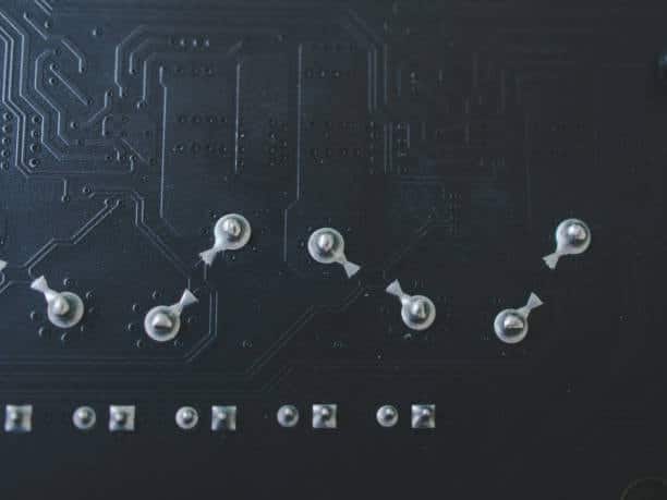
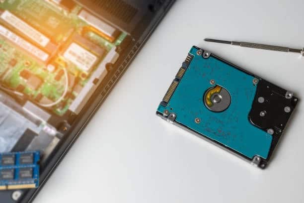
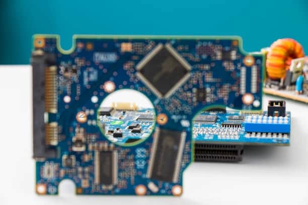
Although through hole technology (THT) remains an essential part of PCB assembly, creating connections that are mandatory for many products, others prefer surface-mount technology (SMT), which is becoming more and more popular each year. Even though advancements in the SMT technology have led to its gaining wider industry acceptance, THT is vital to parts that require great mechanical stability and dependability. As we explore the world of through-hole touch technology in this article, we will discuss the fundamentals of this method, its advantages, and some practical hints for implementing THT in your PCB projects.
Understanding Through-Hole Technology
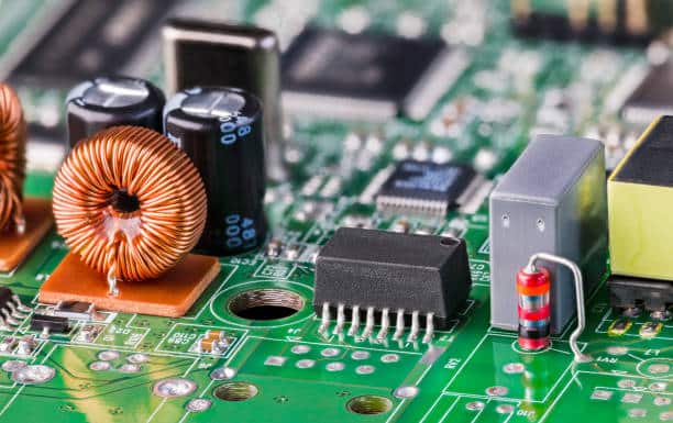
Via holes in thru-hole technology, inserting component leads through holes drilled in a PCB and soldering them on both sides of the PCB. This method induces prejudices and provides good mechanical performance along with excellent electrical connections. It is mainly used for elements that have to have stress resistance, such as connectors, large capacitors, transformers, and so on.
History of the through hole
Through-hole technology had been widely applied in the field of electronics manufacturing in the 1950s and onwards, promising a robust technique for mounting electronic components to printed circuit boards (PCBs). To begin with, components were put onto the material manually using solder, but then, through-hole technology, as it is called, allowed for leads of components to pierce through pre-drilled holes on the PCB and then be soldered to the board. Thus, strong mechanical bonds and stable electric connections were the perfect solutions. So it became possible to fulfill the durability queries.
With time, the evolution of electronics also brought a change in the method of assembling printed circuit boards (PCBs). The 1980s’ saw the emergence of surface-mount technology (SMT), a technique that makes it possible to mount the board components directly onto the surface mount components of the printed circuit board (PCB), hence making the process quicker and the boards compacter. On the one hand, the demand for surface-mount technology grew, but thru-hole mounting remained acceptable for applications where high reliability and durable contact features are called for, e.g., in military, military and aerospace products, and automotive electronics.
Although surface mount technology (SMT) has become the primary approach in electronics, the through-hole approach is still salient for parts that must withstand mechanical stress as well as high power; thus, assembly process skills, including thru-hole, remain a vital aspect of manufacturing and design in electronics.
Through-hole technology vs. Surface mount technology
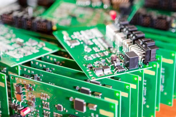
Thru-hole technology (THT) and surface mount technology (SMT) are two different methods of building electronic components onto printed circuit boards (PCBs); however, they both are utilized by totally different approaches.
Thru-Hole Technology (THT):
- Method: Parts contain pads that are drilled in the holes and solidified from the opposite side.
- Strengths: Provides the strongest mechanical bonds and thus is excellent at withstanding mechanical forces or such power transmission components.
- Weaknesses: While potentially providing more flexibility and better SPD performance, it also requires more space on the PCB, which can result in bigger board sizes and may not be effective enough for dense designs.
Surface-Mount Technology (SMT)
- Method: Parts could be placed onto the PCB surface mount devices itself without going through big holes or using bigger pads for fixation.
- Strengths: Provides a greater number of components per area unit, helping to compact circuits and miniaturized circuit boards. The lead time is normally shorter and cheaper than piecework when applied to fasteners in large numbers.
- Weaknesses: The relationships may not be that strong in terms of performance and do not work well in components that undergo serious physical pulling.
As a fact, SMT has become the most popular technology for modern electronics such as mobiles due to efficiency and saving space; however, THT prevails in those situations in which durability and power handling of electronic hardware are paramount.
Through-Hole Characteristics
Also, through-hole technology (THT) is described as the placement of the component leads through the pre-drilled holes in the printed circuit board (PCB) with the soldering on its reverse side.Key characteristics include:
- Strong Mechanical Bonds: Complies with durable bindings—the most utilized joints for tackling physical pressure.
- High Power Handling: Compatible with the use intended as they have a high power or voltage.
- Ease of Testing and Repair: Provides simple, replaceable sections of the equipment.
- Manual and Automated Assembly: Both the hand-soldering sample at the prototype level and the production supporting technologies with automated equipment.
- Reliability: Frequently exists in safety-critical products such as jet engines and computer controls. From Learner’s Corner
Quality Standards for Through-Hole Assembly
The main goals of the QC standards in through-hole assembly are to assess the safety of electrical joints and their ability to function well under different conditions. Key aspects include:
- Hole and Pad Integrity: Making sure that the pipes are in good condition, having the right size, and without tapes.
- Soldering Quality: As such, good solder reflow is not only important for eradicating cold solder joints or solder bridges.
- Component Alignment: The components either in axial lead components or radial lead components have to be meticulously aligned so that the lips are completely filled with holes.
- Lead Trimming: Furthermore, the lead ends need to be cut short to avoid the hazards of short circuits as well as the situation of other parts’ blocked access.
- Inspection and Testing: Carrying out the inspections by visual checking, computer-based visual inspection (AOI), or x-ray inspection for possible defect detection.
- Compliance with IPC Standards: Doing this will make us follow IPC-A-610 standards for the Acceptability of Electronic Assemblies, which supply several soldering specifications, assembly requirements, and mechanical requirements.
Key Benefits of Thru-Hole Technology
- Durability and Strength: The mechanically created bond of THT is more durable than that of SMT; thus, THT is ideal for military and aerospace industries where out-of-stress reliability is celebrated.
- High Power Handling: THT components, mainly resistors, capacitors, inductors, and diodes, are able to withstand a higher power level than their SMT counterparts, which makes them a perfect fit for high-power applications such as power types of circuits.
- Ease of Testing and Replacement: Usually, the manufacture of through-hole components implies ease of testing and replacement, performing maintenance activities, and fault finding.
The Process of Thru-Hole Assembly
This depends on whether we want to perform them manually or use insertion machines. In the case of hand soldering, prototypes and small volumes are almost indispensable, while automated technology is coming into use for larger-volume manufacturing.
Step-by-Step Guide to Thru-Hole Soldering
These are the steps, step by step:
- Preparation: Start by ensuring that your PCB is freed up of dust and other contaminants. To effectively wire your components, insert the leads into their designated holes on the motherboard.
- Insertion: Place the components in the positions that your circuit design says to place them. Bend the leads a bit so that the components stay in an upright position until the whole thing is fixed together.
- Soldering: Use the soldering iron to apply heat to each joint and pour most of the solder into the lead and the pad, making sure that no air bubbles are formed. In fact, thermal management is important to prevent damages.
- Trimming: Once the soldering is complete, take a pair of side cutters and clip all the leads that are left over from the components. You do this so that you can avoid short-circuits or other components being physically interfered with.
Design Considerations for Thru-Hole Technology
Stepping towards THT implementation means designing the printed circuit boards from the beginning. Here are some key considerations:
Hole Size and Pad Diameter: Make sure the holes and pads are fabricated in a way that is related to the other elements. This is the bare minimum prerequisite for successful adherence, something that would also ensure mechanical stability.
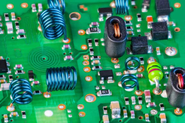
Component Layout: To minimize the overall length of the leads (thru-hole components), place them strategically, preferably avoiding the path or interference of other parts.
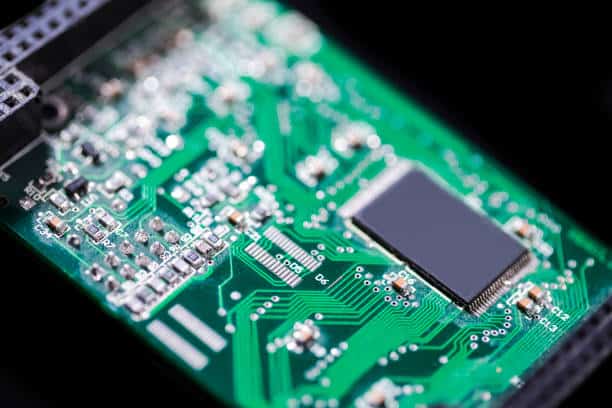
Thermal Management: Think about the heat produced by thru-hole parts in high-power systems. Choose a cost-effective way to cool down the system.
Automated Through-Hole PCB Assembly
Through-hole Automated Printed Circuit Board Assembly is a high-precise and fast process used for the production of PCBs with high volumes. It involves several key steps:
- Component Preparation: Components are pre-made for terminating.
- Automated Insertion: Machines ensure on-time and error-free placement of small components into the holes of PCBs.
- Wave Soldering: By moving forward, the loaded boards hit the cease of the wave solder machine that covers all leads in one go.
- Inspection and Testing: Robotic or visual inspections serve to maintain quality while keeping the product functional.
- Cleaning and Final Processing: Panels are defiberated and checked for final reset.
This method is flexible, fast, arrives at uniformity and is cheap which makes it a good technology alternative where non-breakable mechanical connections are needed.
When to Choose Thru-Hole Technology
While SMT has become the standard for many applications due to its smaller size and cost-effectiveness, there are scenarios where THT is preferred:
- High-Reliability Needs: Shielding and safety are important in these fields, where reliability and hardness are crucial.
- High Power Requirements: Switches THT are built to withstand high power levels or exposure to higher voltages, improving thermal tolerance and contractability.
- Easy Testing and Repair: THT components are simpler, more manual, and more convenient to use, which makes them easily adaptable for prototyping and laboratory purposes where replacements and changes are the most frequent.
- Severe Environmental Conditions: In the event of PCB exposure to vibration, shocks, and so on, THT will provide a more durable and trustworthy electrical planar mounting than SMT.
Testing Through-Hole PCBs
Testing through-hole PCBs typically involves the following steps to ensure functionality and reliability:
- Visual Inspection: Avoiding mechanical defects via component placement, solder quality control, and the removal of any damaged parts.
- Continuity Testing: The most important part is to be sure that each wire is properly connected and there is no open edge, using a multimeter or a continuity tester.
- In-Circuit Testing (ICT): Automated tests to check the shorts, opens, resistances, and capacitance together with all other electrical characteristics of all devices to ensure the functionalities of each component.
- Functional Testing: Simulate a conduction of the PCB systems for the PCB fully powered up. Thus, to adopt the equivalent speed and efficiency during the actual operation system.
- Stress Testing: Simulating the PCB sample with heavy tests including high temperatures, voltage fluctuations, and mechanical vibrations in order to guarantee the required level of endurance.
These tests are able to pinpoint the manufacturing defects and prove that the PCB is going to work as a part in its application.
Thru-Hole Mounting Process
The through hole mounting process for PCBs includes the following key steps:
- Drilling: Holes are made in PCBs through which components are connected.
- Component Insertion: This is how radial leads of thru-hole components are inserted into the holes in these holes or in larger through hole, which are drilled before.
- Soldering: All leads such as wire leads, component lead, axial lead are soldered to the PCB pads at the back of the product for both electrical and manual connectivity. It can be done manually or automatically with wave soldering in high-volume production.
- Trimming: The final leads, which exceed the required length, are trimmed away to avoid shorts and the meticulous appearance of assemblies.
- Inspection: The board is scrutinized for proper component alignment, solder quality, and the proper functioning of all electrical circuits.
This joining technique creates ample and secure connections that are capable of providing such demanding functions as high-power handling and mechanic stresses that components would normally go through.
Thru-Hole Mounting Advantages and Disadvantages
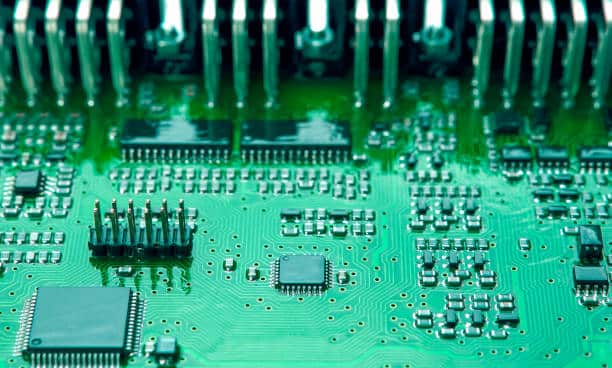
Advantages of Thru-Hole Mounting:
- Strong mechanical bonds enable the withstanding of physical stress, providing a durable connection. Therefore, it can be explicitly used when parts have to endure mechanical stress.
- High Power Handling: Designed to be the best concept for parts that process large currents and voltages due to stronger connections and heat dispersion.
- Ease of Manual Assembly and Replacements:As the components are inserted into their respective areas, complex prototyping and repairs become simple.
- Reliability: Provides the best operations under rugged conditions and even heavy vibration levels and extreme temperatures. Report this error. There is an error in this sentence.
Disadvantages of Thru-Hole Mounting:
- Increased PCB Size: A board needs more parts due to the increased size of components and spacing that requires holes, hence decreasing the size and cost of the PCB.
- Slower Assembly:Manual operations are time-consuming and relatively slow, especially with large volume productions, especially in surface-mount assembly technologies.
- Higher Cost: The price tag usually goes up as assembly of BGA chips is much more laborious and needs more space on the board mount.
- Limited Component Density: It is hard to test the functioning of the components in SMD to a high enough density mainly because of this technology, thus its use in highly compact devices is restricted.
Applications of Thru-Hole Technology
Thru-hole technology is often employed in numerous applications where factors such as longevity, reliability, and good electrical rotation are key. Here are some common applications:
- Military and Aerospace: Such devices should be very resistant to various harsh atmospheric conditions and mechanical loads, which all written-hole component features are due to their perfect reliability and strong electrical contact.
- Automotive Electronics: Thru-tec technology is the go-to application for car parts that have to endure vibrations, dynamic stresses, or thermal cycling.
- Industrial Machinery: The tolerance of thru-hole components to higher power demand and to withstand harsh situations in industrial labor is what makes them more preferable.
- Consumer Electronics: Although thru-hole technology is never used as much as in the past and is mostly used in household appliances and consumer electronics where mechanical stability is needed,.
- Medical Devices: Consistency and accurate performance are the core qualities of these devices that are manufactured using through-hole technology; for instance, heart pacemakers and imaging devices.
- Power Supplies and Converters: These types of components have been specifically designed to be used in high-power applications where they can conveniently handle a large amount of current and voltage.
- Test and Measurement Equipment: Never-ending durability and easy-to-do manual adjustment are the key elements that make the thru-hole elements a preferable choice for such products as the equipment that requires maintenance or change frequently.
The integration of these gadgets has an added advantage since it provides electronic components with the mechanical strength and accuracy needed to withstand harsh environments where physical and environmental stress may be experienced.
Conclusion
The traditional technology is still prevailing through hole boards in spite of the so-called SMT development, as in some cases it’s the PCB that plays a role and the SMT is the one that is replaceable. By learning the time and when to use THT, you will improve not only their endurance but also the performance of your electronics products also in plated through holes. Connection with a rugged environment or reliability of connection will not matter in either way; it is only the ability to master through-hole technology that is equally essential to the PCB designer toolkit.

