Solder Through Hole: An Electronics Basic Skill is a must-have skill for electronics manufacturing and repair. The through-hole method of manual soldering is performed by soldering electronic parts, using a soldering iron or soldering gun, onto a pre-made printed circuit board (PCB). Surface mount technology (SMT) is the go-to technology now, though through-hole soldering is still evident an important technology for applications which have a package that requires either mechanical strength or high power handling capabilities.
In this guide, the focus is on through-hole soldering, equipping yourself with necessary tools and materials, and precise maneuvering of soldering steps for successful solder joints.
Understanding Through-Hole Soldering
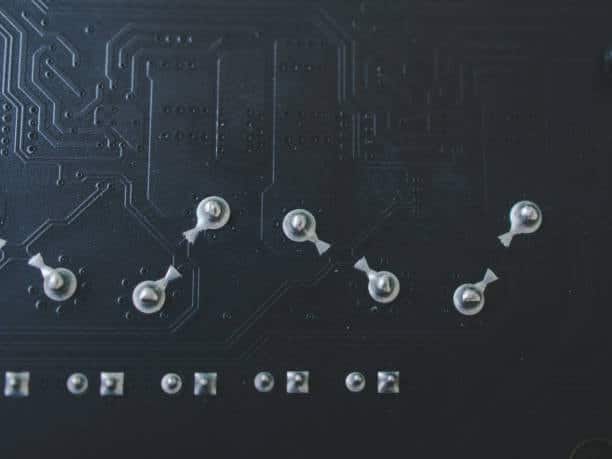
The hole soldering process is of manual soldering, and components are mounting components outside the PCB through the holes that are plated with copper. On the later sides of the board, the leads are guided through the holes and then are soldered on the other side of the board after the components produce power. This method gives a strong mechanical connection and usually instances it for components like etches, connectors, direction switches, and high power components.
Leaded vs. Lead-free Solder – A Brief History
Lead solder is an elemental single-phase substance widely utilized in electronics production for a long time due to its good processing properties. While lead-free soldering eliminated the risk of lead poisoning, which was a side effect of every solder based on lead, it did leave us with environmental concerns which were much more difficult to mitigate.
Lead-free solder became a conventional choice in numerous productions, but it requires extra facilities as for an increase in stabilization temperatures and brittleness. The same as the case with both type solders that have their own benefits as well as weaknesses, so the selection between two will be based on the particular tasks and the regulation followed.
What is Through Hole?
The case of through-hole means a method for mounting and attaching electronic components onto a printed circuit board abbreviated as a PCB. When we know through- hole or through hole soldering it means that this kind of method by which the through hole components are being mounted to a printed circuit board by using physical leads. When we say leads it is being hooked thru hole technology or drilled holes into the circuit boards. The leads then are being soldered into the opposite sides of the printed circuit board just to keep the component leads in place. Wire lead wire are then introduced into these holes and later heated and melted to make a solid union between the PCB and the components on the reverse side.
Through-Hole Capabilities
The advantage of “wired” soldering is that it permits “strong” mechanical connections and, therefore, it is suitable for those components that are subjected to high dynamic loads, stress, or high thermal vibrations. It provides an easier assembly, as well as repairs, of manual variant compared to surface mount technology (SMT) devices but not all components. Despite the fact that through-hole components can perform better power-wise and in terms of handling high voltage levels instead of surface-mount devices (SMT), they are being replaced more frequently by other, more modern manufacturing techniques. On the other hand, hole soldering is commonly slower and has space limitations on mounting highly populated boards that require space for leads and housing around the hole component types.
What is Surface Mount Technology?
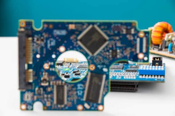
Surface mount technology (SMT) is the approach associated with electronic product manufacturing where parts are directly soldered upon the surface mount assembly of printed circuit boards (PCBs). Contrasting to the through-hole technology in which components have leads placed through the holes and soldered on the board, the SMT components or surface mount components have its leads or tabs soldered directly to the pads lying on the top surface mounted components of the board. SMT offers PCBs with light weight, small area and densely populated with components, hence such a technology is specifically suitable for utilization in compact electronic devices such as smart phone and tablet.
SMT Capabilities
SMT joins electronic components on top of the surface of the circuit board while the through-hole one passes the components through the board. Consequently, SMT results smaller and more compact printed circuit boards (PCBs) than through-hole. It governs the height and footprint of attach components fitted on printed circuit boards (PCBs), so the techincal performance of the electronics can be improved. SMT technology does further by increasing assembly automation without sacrificing the costs and labor efficiency.
What is solder?
Solder is a metal alloy with a temperature that collapses quickly, and it is joined with metal components on most of the time: mostly in electronics and plumbing. Here the metal is presented in the form of a molten fluid and then it cools and unite to create strong and conductive tie between the parts of machine. Soldering alloys is usually made out of a combination of tin and lead but lead-free alternatives, which are also available, can be used as well.
Choosing the Right Solder for the Job
When choosing the right solder for a job, consider the following factors:
- Composition: Rather 60/40 solder (containing both tin and lead) is more suitable for making joints between different copper surfaces, so-called lead-free solder is much more environment-friendly. Select what you need and be comply with the regulations. Write a stellar sentence that describes the charm of the city and its reasons to be cherished. Showcase the city’s delightful attributes and its significance to the residents’ lives.
- Melting Point: Choose based on the solder’s melting point a solder which is suitable to the parts and the PCB materials. Nonlead (Pb) based solder normally has a higher melting point.
- Flux Core: The flux bobbin allows flux to flow into the solder. It helps clean and promote the flow of solder. Determine for what purpose and how much flux the miner should be using.
- Wire Diameter: Make a custom selection of the lead wires gauges used that match the size of the components and pads thus adding to soldering control.
- Quantity: Enough of solder needs to be bought in order to avoid both waste and to run out during the entire project.
- Brand/Quality:Think of a solder brand’s peerage and quality not to have your performance fall up short and be inconsistent.
What Is The Standard Of IPC Through Hole?
When it comes to via technology, the IPC standard ipc-A-610 specifically focuses on acceptability criteria for the assembly through-hole mounting persisting components on the printed electronic circuits.
Types Of Through Holes
There are several types of through-holes used in PCBs:
Plated Through-Hole (PTH)
Holes filled with copper, enough for components to be pasted on and soldered from both sides of the board.
Non-Plated Through-Hole (NPTH)
Sections after holes which are not plated and are used for mechanical features or positions for bolds.
Blind Via
A hole to an outer surface of PCB that puts it in connection with one or more inner layers of PCB but does not pass through to the other side of the board.
Buried Via
A through hole boards that will take its course to at least one or more inner layer of the track but will not terminate to the outer layers or multi layer pcbs.
Thermal Via
A shining black piece that does a good job at transferring heat away from module pieces.
Basic parts that make up a soldering iron
A soldering iron consists of the following basic parts:
Handle
The end of the soldering iron that holds the triangle-like shape, which is similar to the one of the triangle-shaped end of the iron. It’s usually non-sticky and produced out of resistant to heat material and comfortably holding it.
Heating Element
This part is responsible for the generation of heat which occurs when electricity is channeled through it. The usual elements of the heating system is the ceramic and metal alloy.
Tip
Branded as a soldering tip/ bit, this is the object that has to go in direct contact with the solder and the components to be soldered. The tip of this grooved tool may be solid or made of copper which may vary widely in size and shape depending on the task to be done.
Power Cord
The power cord dangling loosely from the soldering iron to the power source. Nominally, the energy source is an electric supply, which then drives the heating element.
Temperature Control
Some soldering irons are equipped with a temperature control feature which lets the users set and control the soldering iron tip temperature. That helps with the different soldering applications without unwanted damages of delicate devices.
Stand
A stand or bracket that will hold the soldering iron in a one place and stable when it not used. Furthermore, its role in protecting personnel from accidental burns as well as the work surfaces from potential damage cannot be underestimated.
Cleaning Sponge
A sponge or brass wire cleaner is used for cleaning the soldering tip, removing solder and oxidation to assure good heat transfer and quality of soldering.
Safety Features
Auto-shutoff may also be available in other safety features of some soldering irons, now, these can come under the unmentioned category.
Two varieties of wands
There are two main varieties of soldering irons or wands:
- Simple Soldering Iron: This kind is a plain soldering tool, in which a handle, heating element, and fixed tip are integral. It is used widely for simple soldering jobs and it usually does not have any temperature control or tips that can be changed.
- Temperature-Controlled Soldering Station A soldering station with hot air rework, that consist of the base station and a detachable soldering iron with a variety of tips. The base station maintains the iron temperature that provides for exact temperature control according to the soldering needs. These are the stations that people prefer using while working with complex soldering tasks and while dealing with sensitive components.
Two variations of a soldering iron base
There are two main variations of soldering iron bases:
- Basic Stand: An elementary stand comprises of a plain metal or plastic base with a socket for the soldering iron. When not being used the soldering iron is kept in the holder, which ensures stability and eliminates chances of burns or damage to any kind of surfaces.
- Temperature-Controlled Station: A temperature controlled station consists of a base unit with a temperature control knob or digital display. The base unit controls the temperature of the soldering iron in order to provide uniform and precise heating. Precision soldering tasks and working with temperature-sensitive components are best done in temperature-controlled stations.
Different types of iron cradles
There are several types of cradles or stands used for holding soldering irons:
Basic Stand
The basic stand includes the dead basic metal or plastic stand with the holder for the soldering iron. It brings support and keeps the iron standing when idle.
Spring Stand
A spring stand employs a spring mechanism in holding the soldering iron. The spring permits the ease of taking out the iron and putting it back in the position it should be.
Sponge Stand
A sponge stand comes with a sponge or brass wire cleaner which is used to clean the soldering tip. Usually, the stand has a space or pocket for the sponge which is easy to use for wiping the soldering tip during the working process.
Magnetically Attached Stand
Some soldering irons have a stand that connects to the iron using magnets. This kind of stand offers a steady grip and also allows for an easy and quick ironing on and off.
Adjustable Stand
The user can easily change the angle or position of the soldering iron using the adjustable stand. Such stand is quite convenient during the long soldering hours.
Soldering Accessories
Soldering accessories include a variety of tools and supplies used in the soldering process:
Solder
A metal alloy that melts at a low temperature used for bonding metal parts.
Flux
A sold fluxing solution that assists the solder in flowing and adhering to the metal surfaces.
Soldering Iron
A device that is used to heat the solder and components to be joined.
Soldering Station
A master unit that sets the temperature of the soldering iron as well as giving a solid platform for soldering.
Soldering Tips
Soldering iron tips, which are interchangeable, are offered in many shapes and sizes for different soldering needs.
Desoldering Pump or Solder Wick
Solutions that will either inducting cooling or cleaning solutions which will remove the excess solder or the desoldering components.
Soldering Mat
Utilization of tools intended to salvage solder or to disassemble components.
Helping Hands
A heat-stress mat made in order to prevent any heat damage to the surfaces during soldering processes.
Cleaning Sponge
The soldering jig granting components to stay in place using alligator clips, attached pieces.
Fume Extractor
The tool is applied to extract the fumes produced by soldering from its working area, thus preventing the passages of toxic inhalants into the worker’s air passages.
Two main types of through-hole components
The two main types of through-hole components l are:
Axial Leads
The axial lead components elements are characterized by the existence of the leads on the ends of the element in a straight line. Through those they are connected with pins on the PCB both sides and soldered to axial components just like axial leads run.
Radial Leads
Radial lead components lead among the components have leads that spread in the sides of the component body to the radial components. The pins of the components are inserted into the corresponding pliers holes on the PCB to be soldered to one side only, with the component body flat against the PCB.
What are the steps of how to solder a through hole components?
Here is a summary of the steps to solder a through-hole leads component or to the solder mask relief:
- Prepare the PCB assembly
Secure the PCB well on a stable surface where it can be observed and the surface is also clean and dirt free. - Insert the Component leads
Insert the through-hole component leads into the same holes where the PCB components were earlier. Make sure you position the piece in an appropriate manner. - Secure the PCB assembly
Clamp or use the holder to fit the PCB nicely and it shouldn’t move much while soldering. - Heat the Joint quality
Heat the soldering iron and hold the tip at the joint where component lead meets the copper pad PCB. Warm both the lead and the anvil. - Apply Solder
Now, take the solder and put it onto the joint after it gets warm. The solder should melt and run all around the lead and pad, forming a joint which will be a good connection. - Remove the Iron
Turn off the soldering iron once you have accomplished soldering the joint. Support the component lead with your hand so that it won’t tip until the solder completely solidifies. - Inspect the Joint
Take a closer look of the solder joint to ensure that it has been made correctly and is smooth, shiny and concave. Iterate (repeat this process) for the rest of your leads. - Clean the PCB assembly process
Apply a brush or blow the flux residue off your PCB through the compressed air.
Advantages Of Through-Hole PCB Assembly
The advantages of through-hole PCB assembly include:
- Mechanical Strength: The through-hole components plugs result in stronger mechanical connections, therefore the components are more resistant against mechanical stress and vibration
- Heat Dissipation: Compared with surface mount technology, through-holes are good at thermo-dissipation, and they can be used in the high-power application.
- Ease of Assembly: Through-hole components coming with the better handling and manual solder properties are mechanically suitable for prototype and first production steps.
- Repairability: Through-hole components are more convenient for repair and replacement than surface-mount components, therefore, board maintenance becomes easier.
- Compatibility: Through-hole parts are aging-compatible with existing PCB designs and older production processes, which means that they can be a good choice for legacy systems.
Limitations Of Through-Hole PCB Assembly
The limitations of through-hole PCB assembly include:
- Size and Weight: The via-hole part, being large and heavy in weight, is a setback that might prevent the design of small electronic hardware systems to be possible.
- Cost: Through-hole assembly is, by nature, the costlier method compared to surface mounting as it has to, on top of the soldering, also include drilling and vertically inserting the components into the circuit board.
- Signal Integrity: These earring components are usually huge enough not to give birth to signal distortions and impedance mismatch issues at high frequencies.
- Board Density: With lead through-hole components, more space needs to be included on the circuit board and, as a result, fewer components can be placed on the given circuit board area.
- Obsolete Technology: Through-hole assembly is becoming more and more an exception in the modern electronics. Designs of those kind make it impossible to find components and also support for the through-hole designs.
Through Hole PCB Assembly Design Considerations
When designing a through-hole PCB assembly, consider the following key factors:
- Component Placement: Place together elements to ascertain that your signal paths are of minimum length and cramp issues. Ensure enough margin between the components for the entire process to be smooth and no short circuit to happen.
- Trace Routing: Make sure traces are wide enough for the expected current draws and routing is well planned to decrease the signal noise and crosstalk creation.
- Thermal Management: Provide the thermal relief for the through-hole pads so as to shorten the soldering process and ensure the components are safe from the accumulation of heat.
- Hole Size and Plating: Take care to use the right size hole and also to properly plate the hole to prevent lifting of solder joints and mechanical destabilization.
- Component Orientation: Orient the components in such a way that the assembly processes are not only manual assembly but automated as well as the correct alignment to other components will be maintained.
- Board Thickness: Select the board thickness, to meet the strength requirements and also provide enough space to allow passing of through-hole components, without this going beyond the maximum expected thickness of the material to be used for your application.
- Compatibility with SMT: Think about over-molding compatibility with the surface-mount component and processes, if you at some point need to use both through-hole and surface-mount components on the same board.
- Testing and Inspection: Layout the board to help tests and inspections of thru-hole solder joints for those approved quality and credibility.
- Component Availability: For example, give attention to the fact that through hole components may be extremely hard to find, given that some of these may not necessarily be equivalent to the same surface mounted parts.
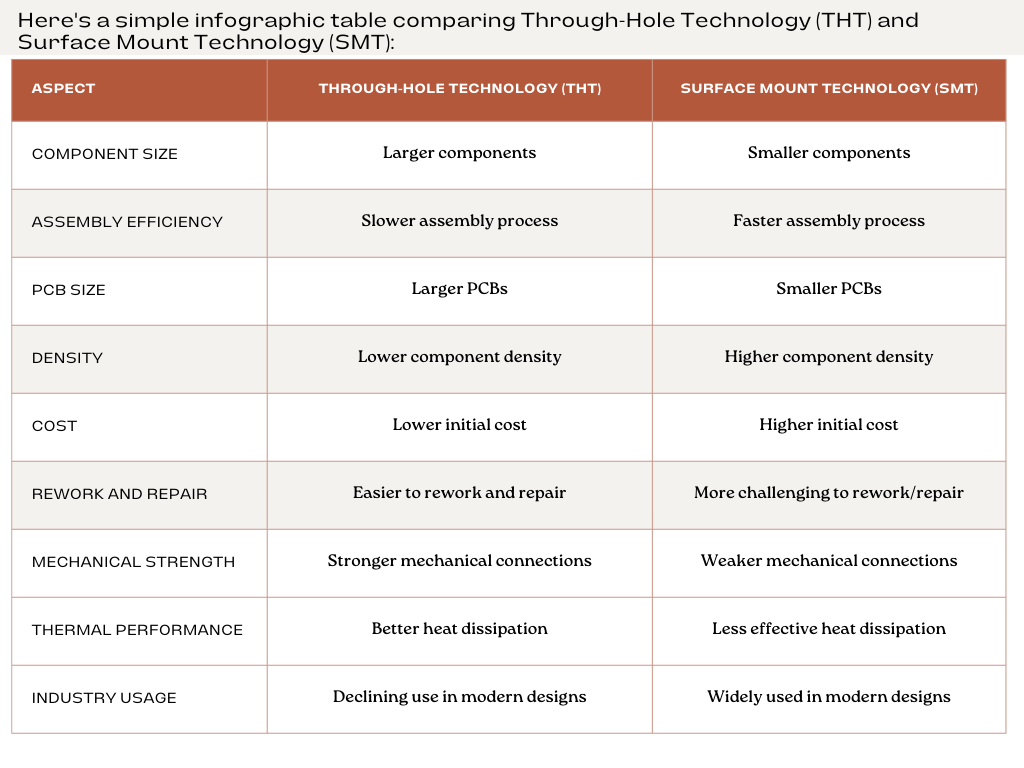
Comparing Through-Hole Technology (THT) And Surface Mount Technology (SMT) infographic

Conclusion
Through-hole soldering expertise is like a precious tool for an electronics worker. Mastering the principles of through hole soldering and using the guide as a reference manual will help you to get good joints that are a must for any good electronic product to function and last for a longer time. When we know through- hole or through hole wave soldering it means that this kind of method by which the through hole components are being mounted to a printed circuit board by using physical leads. When we say leads it is being hooked thru hole or drill hole sizes into the circuit boards. The leads then are being soldered into the opposite sides of the printed circuit board just to keep the component leads in place. Having practiced patience and close attention to the process, you will become skilled in the key of solder through-the-hole technology and you will be able to make more complicated electronic projects with certainty. Known originally as “planar mounting,” the method was developed in the 1960s and has grown increasingly popular since the 1980s. The parallel leads projecting from a single mounting surface gives radial components an overall “plugin nature”, facilitating their use in high-speed automated component insertion (“board-stuffing”) machines. In the past, components with long leads would be inserted, usually by hand, into plated through holes on the PCB which in the past use this in the military and aerospace industries and then test and prototyping applications.


