Know about how to recognize the cold solder joints in an electronic component and learn how to do solder alloy flows properly using soldering irons to solve them and try to avoid it in the future. Conduct researches and generate manuals which will inform people on the subject of soldering techniques.
What is a cold-solder joint?
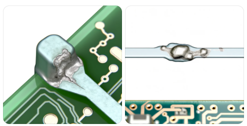
A cold solder joint is a type of error that is prevalent during the soldering job, predominantly involving electronic units. In soldering, the process of connecting two metal surfaces is that soldering iron with its molten solder is used to fill the gap, and the solder melts, which eventually solidifies to permanently form an unbreakable electrical and mechanical joint. On the other hand, incorrect heat management can cause cold joint failure.
What are the key features of a cold-soldered joint?
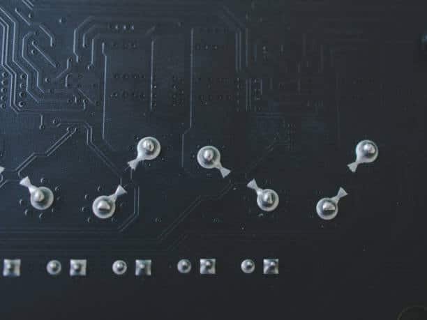
- Dull appearance: Unlike a solder joint with a flawless shape, whose surface is shiny and smooth, a solder joint that is still liquid looks dull and can have a grainy texture to it.
- Lack of proper bonding: The solder material fails to melt and produce a strong joint with the surfaces, causing electrostatic insulation and poor mechanical stability.
- Weak connection: This solder joint does not have enough bonding, so it becomes intermittent and can lead to complete circuit board failure.
- Potential for failure: A cold solder joint can fail, and malfunction of the device will occur, or it will not perform its functions properly if this joint becomes weak due to its rough or lumpy surface.
To avoid very cold solder joints, it is necessary to follow good soldering techniques, for instance, appropriate heating of the solder and surfaces, the use of sufficient flux to promote fusibility and obtain a good bond, and clean and well-prepared metal joints for soldering.
What are the types of cold-soldered joints?
There are a few variations or types of cold solder joints that can occur during the soldering process, each with its own distinct characteristics:
Fillet Cold Solder Joint
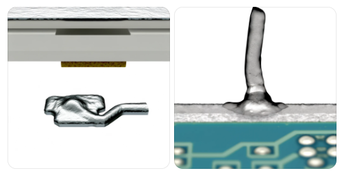
The solder drip joints type do not get covered evenly with good-quality solder paste to form a fillet around the joint. On the other side, it will seem disorganized and uniform, provoking a lack of requisite adhesion to the metal surfaces.
Grainy Cold Solder Joint
It forms a craggy, rough surface on the solder pad, which is unusual for the smoothness of the solder points. This phenomenon is the result of the corrosion of the solder, which does not properly mesh the two metal surfaces, resulting in insufficient connection in the solder joint, which leads to solder joint failure.
Underfilled Cold Solder Joint
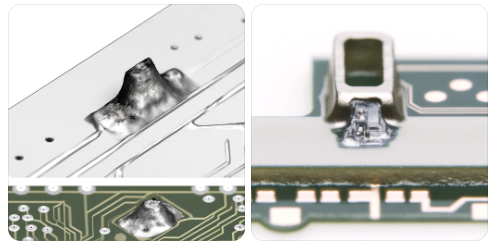
If an underfilled lead-free solder alloy in the joint is present, the amount of solder on metal surfaces is too small to ensure a complete cover and bond. Such happenings may result in gaps or breaks in the joint, thereby reducing the aesthetic function of the solder alloy in the joint.
Brittle Cold Solder Joint
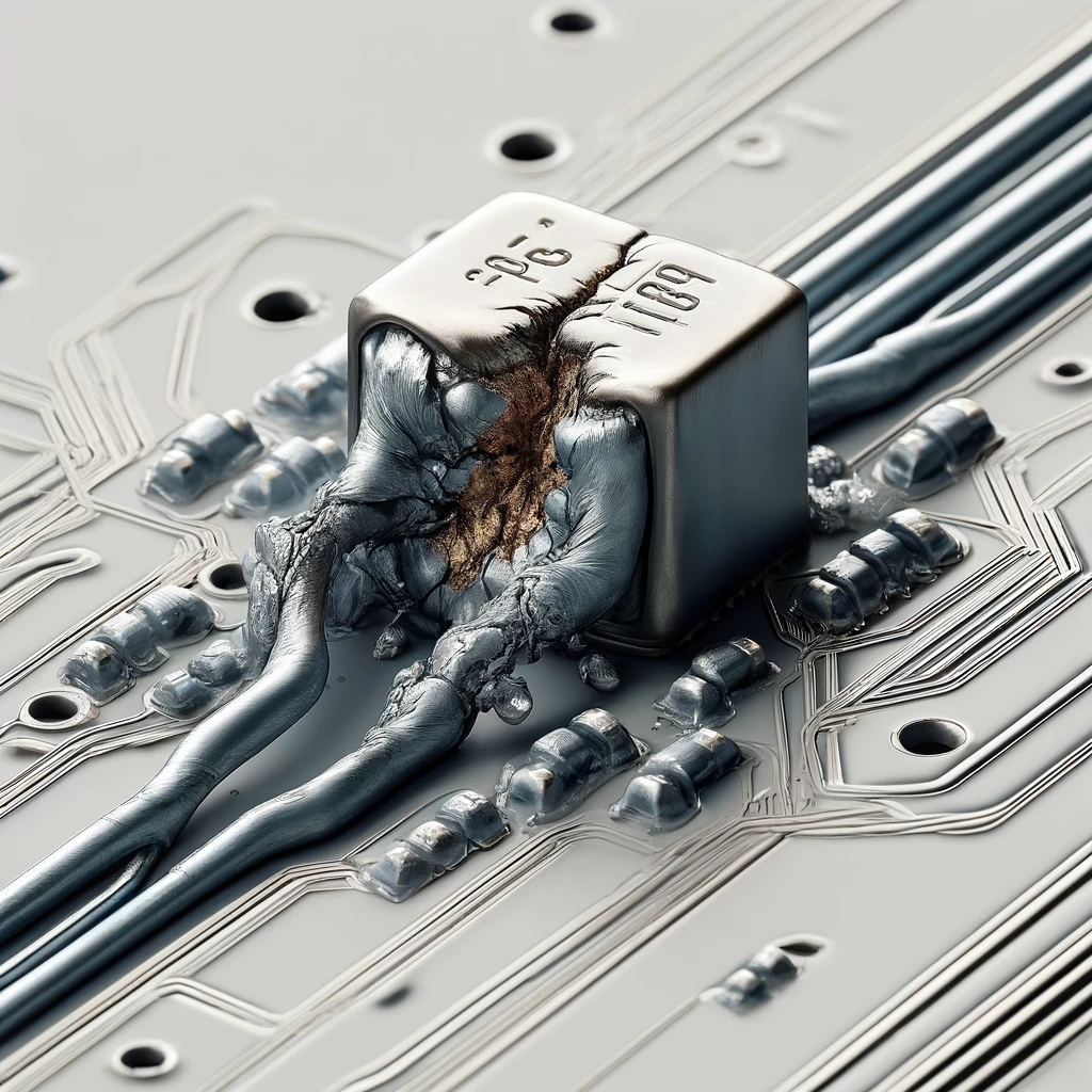
Flexibility of solder wire failing the brittle soldering connections is worse than that which tends to crack or break easily under stress. It happens when the solder in the cooling process does not melt properly and does not have enough time to form a robust ductile link with the metallic surfaces. It is best to have a cathode ray tube in your soldering station, as it can significantly reduce vibration, which lowers the risk of solder cracking.
Locating these specific types of cold solder joints during the diagnosis and confirmation of the reliability of the soldering cold solder joints in electronic assemblies is of major importance. Adequate heating, the presence of flux, and surface preparation are all preconditions of good soldering techniques that can contribute to the prevention of the formation of cold solder joints.
What causes a cold solder joint?
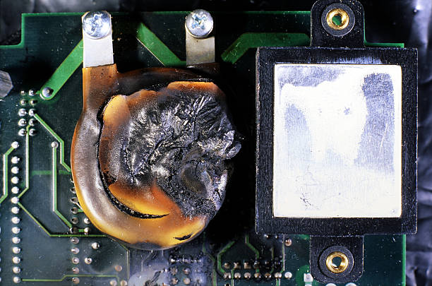
Several factors can contribute to the formation of cold-soldered joints:
1. Inadequate Heat
In such a case, though the soldering iron or point source does reach the peak temperature, the alloy’s melting point, there is a probability that the dry solder joint or the metal surfaces being joined won’t be sufficiently heated or melted. This kind of bonding stays incomplete, and the formation of cold solder joints is the result of this kind of bonding.
2. Poor Flux Application
Flux is a critical factor that supports soldering because it helps evict the oxides from the surface of the metal and lubricates the solder flow and adhesion. If the flux is applied in excess quantities or when the flux is ineffective, then the soldering problem of bad solder joints occurs, and if insufficient wetting or bonding occurs,.
3. Dirty or Oxidized Surfaces
Applying solder alloy bonding to metal surfaces needs to be achieved on clean and oxide-free surfaces. Oxides or contaminants are not allowed on such surfaces. If the surfaces are filthy, oxidized, or cracked and the solder is poorly grounded, the solder may not stick together well, giving dry solder joints.
4. Improper Soldering Technique
More specifically, the use of incorrect soldering techniques like lack of solder coverage, excessive amount of solder applied, or incongruent soldering angle can lead to the formation of cold solder joints.
5. Rapid Cooling
The solder needs certain time to fix well or to shape a firm joint. If the solder cools too much solder too fast for reasons like no preheating of the components or interference of cool air, it will not connect well as little solder alloy is with the surface parts, resulting in a cold soldered joint taking a sufficient amount of time.
6. Component Movement During Cooling
Lifting and relocating components while the solder has not completely solidified can interfere with the formation of cold solder connections and dry solder joints together, and thus there will be a risk to the cold solder joints.
7. Low-Quality Solder or Flux
A cheap lead-free solder and flux with less wetting or bonding properties often result in cold soldering, making the joint weak.
How do you detect a cold solder joint inside your PCB assembly?
A cold solder joint in a printed circuit board (PCB) assembly perfectly defines a key element of proper device reliability. Therefore, it has to be carefully detected. Here’s how you can identify them:
- Visual Inspection: Carry out a clean look at the solder joints exposed on the PCB. Search for clouds, speckles, or the business of metal, which is opposed to the smoothness and glossiness of a well-soldered joint. Visual abnormalities like these help the cold solder connections get noticed and separate from the regular ones.
- Physical Inspection: Carefully press the solder joints onto the metal using a pointed tool or a fingernail. A satisfactory joint should be well-soldered and firmly fastened to the circuit, while a cold-soldered joint may be sloppy and easily detached. Any change, such as a movement or a twist, might be a red flag of dysfunction, too.
- Magnification Tools: With the help of a magnifying glass, magnifying lens, or microscope, carefully examine the soldering to see if there are any flaws. Defects such as voids, incomplete soldering, or a lack of uniform solder pooling that remain undetected to us by the naked eye may be the cause of fabricated microchips failing during activation and operation.
- Electrical Testing: Use a multimeter for a few testing procedures in test terminals, such as continuity or resistance heat testing across the solder joints. Open terminuses may rotate around, form intermittent connections, or have higher resistance, and thus they can imply a problem.
- Thermal Imaging: Use the thermal camera or the handheld infrared thermometer to locate thermodynamic changes on the printed circuit board assembly. Solder joints, which were insufficiently strong, have demonstrated an abnormality in the heat transfer process resulting from a lack of thermal conductivity compared to the other areas of the joints.
- Tap Test: The PCB board gives a signal by tapping or shaking the board while listening for any strange type of sound. This might result in a characteristic sound in an agitating way because of the weak adhesion of cold solder connections.
- Reflow Testing: The reflow soldering process may be subject to a controlled reflow process where the solder is again reheated to reflow temperature. The concerned solder joints can experience multiple failures, including the failure to reflow properly, even if they remain visually unchanged or have minimal reflow effects compared to surrounding joints.
By employing these methods, you can find the bad solder joints on a PCB and take the right steps to solve the excess solder voids, making electronic devices that work as expected and are reliable.
How do you service your PCB if cold solder joints occur?
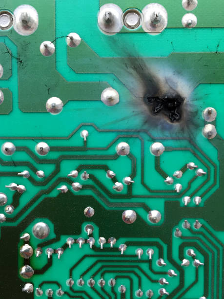
If the solder fails to adhere properly to a component on the PCB assembly, the circuit board must be serviced without delay to ensure the proper functioning and reliability of the electronic device. Here’s how to service your PCB:
- Identify Cold Soldering Joints: Sampling will be done by visual inspection, magnification tools, and methods such as ohmmeter testing. Ohmmeter testing is used to identify cold-soldered joints. The weak power, no electrical resistance, grainy looks, and weak connections are the obvious signs of worn-out batteries.
- Prepare for Repair: Get your soldering tools and equipment ready, including soldering iron, solder wire, flux or solder paste, desoldering wick or pump, heat-resistant gloves, safety glasses, and others suitable for this one.
- Desolder Cold Joints: Resolder using a desoldering tool or desoldering wick to pull out the solder from the cold joint that has solder bridges on the soldered pin. Use the soldering iron placed on the joint, and then sponge up the liquefied solder with the desoldering tool or wick.
- Clean the area: Disconnect the component from the electrical system and remove the old solder. Next, clean the area around the cold solder joint with isopropyl alcohol or a similar solvent to make sure there are no flux residues, waxes,wax or dust particles that may hinder or cause future issues.
- Apply Flux: Correcting the cold solder joint by applying a little flux to the place around where the joint is soldered would be enough. Solder flows and wicking flux are designed for the right amount of completion of a solid joint. The quality of a bond depends on a homogeneous solder per metal surface.
- Soldering: Solder the raised junctions to form welded parts. Use a good soldering iron at the proper peak temperature and heat the metal surfaces to the joint. When applying solder to the joint, make sure it has enough coverage, while each joint should be neat and shiny. To avoid getting a cracked solder, try not to stress the joint with excessive heat, as it may damage tissue further.
- Inspect and Test: Finally, after soldering, visually inspect to see if the “glued” part has a nice, shiny finish and attachment. See if you could check the electrical properties, if possible, so as to check the integrity of the joint and its electrical connection.
- Reassemble and Test: Finally, when we inspect the PCB for cold solder joints and repair those areas if necessary, the device is reassembled and functional testing is conducted to confirm that the gadget operates as intended.
What are the best practices in soldering to prevent cold solder joints?
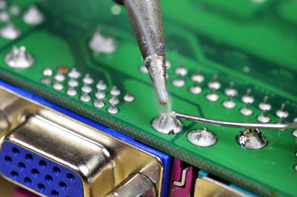
To avoid cold solder joints and ensure strong, reliable connections in soldering, it’s essential to follow these best practices:
- Proper Heating: Be sure that the soldering iron reaches the proper temperature for soldering and de-soldering the components used. The solder has its optimal melting point and flow in sufficient heat conditions, which makes the solder stick to the metal surfaces much stronger.
- Use of Flux: Fuse the metal surfaces with appropriate flux before placing the solder from the solder spool. Flux plays a huge role in removing oxides, contaminants, and impurities. Once the surfaces are wetted, the bonding between the solder and the surfaces is formed.
- Surface Preparation: The solder surfaces should be carefully and completely cleaned and prepared before soldering. Clean the surfaces from dirt, oxidation, or any residue using the solvent or abrasive that you wish to use so that you can achieve the best adhesion and conductivity.
- Correct Soldering Technique: Make use of the right soldering technique—that is, solder wire feeding should be correct and soldering iron angle should be ideal. The soldering procedures are performed by fixing up a steady contact between the soldering iron tip, solder, and metal surfaces. This helps to ensure that the heat is evenly distributed and there is a continuous solder flow.
- Avoiding Rapid Cooling: Eliminate thermal shock and rapid cooling of the soldering joint by providing enough time to naturally solidify a solder joint after the soldering process. It is recommended not to touch or move the joint until it has completely cooled off, since in this way, uneven fragments can break away and attach.
- Component Positioning: Make certain that all components are correctly positioned before you start soldering. Adding stabilizing components stops the component from moving when it is being soldered; thus, it is the solder joint that gains and does not break due to component bending.
- Inspection and Testing: Perform visual inspections and functional checks on a regular basis in order to search for any possible problems, including faulty joints. Employ test terminals on magnifiers and continuity testing mechanisms to ascertain the soundness of soldered connections.
- Training and Practice: Giving sufficient training to the workers in soldering activities is imperative. Automation of processes in soldering patterns leads to an error reduction in cold soldering joints proportional to proper soldering technique knowledge and handling of equipment.
Conclusion
In conclusion, cold joints may be listed as the leading problem of soldering apparatus in electronic devices, and this issue may cause low reliability of electric units. A few reasons behind these joints are heat or flux deficiency and inappropriate soldering methods, which result in an inadequate bond with the metal surfaces. A spotty and lumpy surface with a rough visual aspect and low and weak electrical resistance is common among dry solder joints that may show intermittent effects or mechanical failure eventually.
The detection and handling of bad or cracked solder joints is realized by means of visual, physical, and proper soldering method demonstrations and the adoption of reliability principles as a way to ensure the functional integrity of electronic assemblies. Good practices such as heating the area properly, perfect flux application, surface preparation, and component positioning can decrease the possibility of cold solder joints and strengthen the electronic devices’ bonding points and soldering capability too.

