When it comes to electronic assembly, two primary methods have dominated the industry for decades: with (SMT), which designs smaller components, and through (THT), which uses bigger elements. Each of the strategies has its strong and weak sides. That is why, in some cases, farmers need to consider these factors: application, cost effectiveness and assembly.
We will take a look at how the two approaches differ in this article and touch on their advantages and disadvantages.
What is Through-Hole Mounting (THM)?
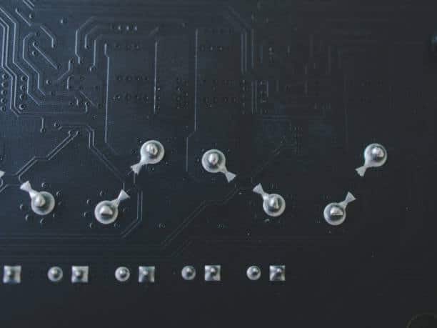
Through-Hole Mounting (THM) stands for the technique of mounting electronic components to a printed circuit board (PCB), where the component leads are inserted into pre-drilled holes, after which they are soldered down to pads on the other side of the board. By this way, critical stress and strong mechanical connections could be obtained and when SMT is not practicable or simply because of the requirements of some components, this method will help and be useful.
Axial vs. Radial Lead Components
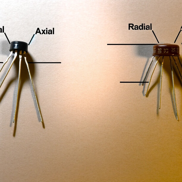
Axial Lead Components
Axial packages present leads whose electricity-conducting material is peripherally parallel to the body of the component. Their primary application is usually to assemble through-hole-mounted parts such as the wire-lead entering pre-drilling holes on the PCB from one side and the wave soldering on the opposite side. Simple layout structures are typical for axial leads and are common in resistors, capacitors, and diodes.
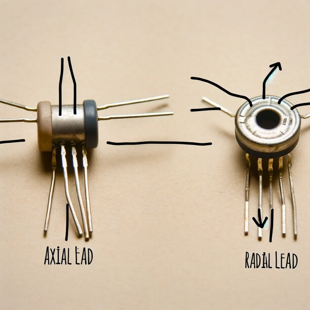
Radial Lead Components
If the leads are located at the edges of a surface-mount component, it is referred as a radial lead component. In through-hole mounting, the leads will be inserted on the PCB printed circuit boards holes, while in surface mount, the leads will be soldered directly on the PCB surface. These conical-shaped connectors are most likely to be encountered in electrolytic capacitors and some diode types.
Advantages and Disadvantages of Axial vs. Radial Lead Components
Advantages of Axial Lead Components
- The component for soldering through the pins offers right mechanical support.
- Besides finding alternatives to the radial lead components, the CRT technology turns out to be a more budget-friendly option.
- More durable in extreme temperatures due to the seeming construction.
Disadvantages of Axial Lead Components
- Huge dimension in comparison with typical angular lead components are affected by the fact that they occupy a great deal of space and therefore used for larger designs rather than by compact ones.
- Lower efficiency for plastics molding to make automated platforms to assemble, reducing production and increasing cost.
- For old devices, procuring the latest components has become more of a challenge because the industry now adopts surface mount technology
Advantages of Radial Lead Components
- The installation of components can be done in two patterns, that is, through-hole component or surface-mounted, giving variety to PCB design.
- size of axial lead components is smaller relative to the ones grown, making them suitable for compact designs.
- It can be used to increase the automation of the manufacturing process and cut down on labor time and costs.
- These surfaces are readily available for use and also match the flow of modern PCB fabrication.
Disadvantages of Radial Leads Components
- Lower mechanical stability in a situation of radial lead component mounting via the mounting holes drilled instead of the axial ones.
- These wires are more prone to damage during shipping and installation because of their lengthy lateral wires.
- They are frequently in the range between axial and leadless components but generally fall at the expensive side.
- Smaller power handling ability when compared with some leads ( axial).
Cost Savings Through Hole Technology
Sometimes through-hole technology delivers the cost benefits of low-run introductions or the use of commonly available components in surface mount technology allowed by through-hole packages. In contrast, when volumes of manufacturing are high, conventional SMT is more efficient since it is facility-intensive and equipment-heavy, resulting in speedy assembly times.
Applications and Use Cases for Through-Hole Technology
- Prototyping: The through-hole technology is widely used in prototyping electronics as it is known for its convenience in setting up the circuit complexity and re-placing the components.
- Repair and Rework: Through-hole components are easier to remove and fix with a wrench, making them more suitable for repair and similar operations.
- High-Reliability Applications: When it comes to applications where mechanical strength and reliability are mostly of concern, through-hole components are commonly used.
- High-Power Applications: The use of through-the-hole components can be useful in applications that require higher power levels than some surface-mount components.
- Harsh Environments: Feed-through hole components can satisfy the requirement to resist extreme factors like heat, vibration, and moisture to function in a more complex process environment.
- Compatibility: Most of these components, especially the old or very specific ones, can only be procured in through-hole packages, whereby through-hole technology becomes the only solution for certain projects such as PCB design or PCB assembly.
- Education and Learning: The education context is regularly designed with through-hole counterparts and manual soldering technology to aid learners in becoming experts on early electronics assembly or manual adjustments.
What is Surface Mount Technology (SMT)?
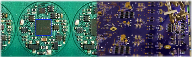
Surface-mount technology (SMT) is one of the methods used to assemble electronic circuits where devices are attached directly to the PCBs’ surface. This constitutes a difference from through-hole technology, which is about component leads that are placed in the holes and the latest solder. The loT elements are on a small scale, which is why a higher number of components can be embedded and small PCBs are being used, and the components are put into place using pick-and-place machines for high production.
Different aspects of surface mount technology
Surface Mount Technology (SMT) constitutes of various principal points; half the manufacturers use SMT today, among others. Here are some key aspects:
- Component Size and Density: SMT technology parts have much lower dimension than through-hole components; therefore, great component high density on the PCBs could be achieved. Therefore, the application facilitates the creation of such miniaturized and more compact electronic devices.
- Assembly Process: SMT process with surface mount parts; the same process is automated with the help of auto pick-and-place machines. Such technique is quicker and more accurate than snipping through-hole soldering, making it a more widely used choice than high-production techniques such as multilayer through-hole soldering.
- Cost-Effectiveness: SMT assembly is mostly cheaper than THT assembly; the higher the volume of production, the more probable it is. The automation assembly lines not only reduce labor expenses and losses in materials but also improve the economic stability and sustainability of the industry.
- Design Flexibility: SMT not only gives freedom to the designers but also enhances creativity in board layouts and designs because components can very well be placed on both sides of the board. The achievement of this flexibility may result in considerable space savings on PCB.
- Higher Frequencies: SMD parts are highly apt for high-frequency decays since they have a lesser rate of collisions as perceived for through-hole parts.
- Improved Electrical Performance: SMT parts normally provide superior electrical parameters due to the fact that SMT has shorter traces, lower parasitic capacitance and better signal integrity.
- Thermal Considerations: SMT diodes are better than through-hole ones in dissipating heat thanks to their smaller size and shorter distance to the surface-mounted components of the PCB.
- Environmentally Friendly: SMT assembly consumes fewer materials and requires fewer energy sources than the through-hole assembly method; hence, its nature is deemed eco-friendly and reduces environmental stress.
Common of Surface Mount Devices (SMDs)
Common Surface Mount Devices (SMDs) include:
Resistors
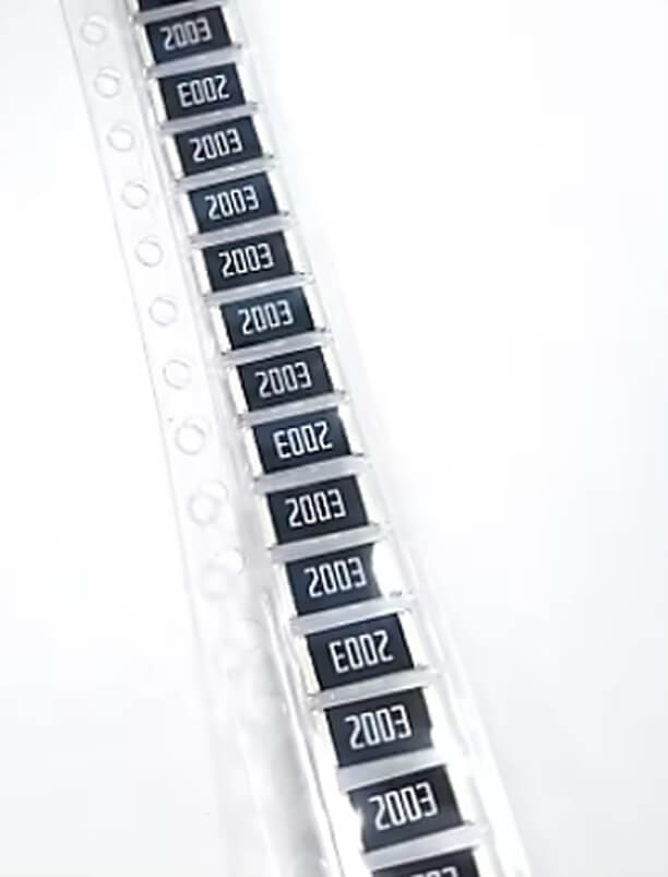
SMD resistors are thin, small and rectangular in design and they attach with the help of the two metal terminals. They can have different sizes and resistances in terms of them.
Capacitors
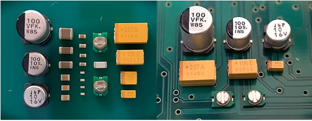
SMD capacitors could be ceramic, tantalum, or electrolytic, and they range in different types. They are playing the role of a reserve for the retained electrical energy within the circuits.
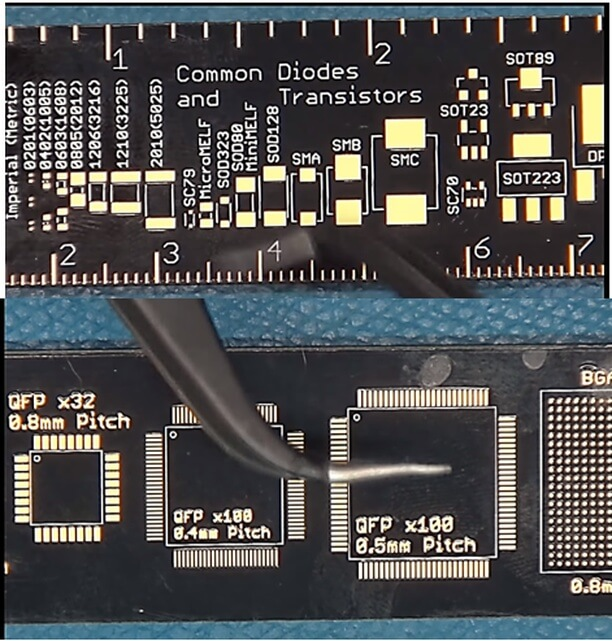
Diodes
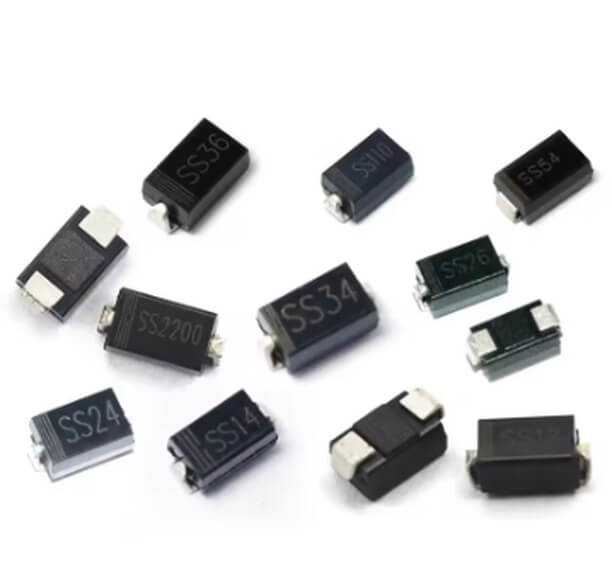
SMD diodes are able to direct the route a current follows in a circuit. They can be different kinds, such as Schottky diodes, Zener diodes and light-active diodes (LEDs).
Transistors
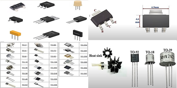
SMD transistors are more useful than ever now as semiconductor components that amplify or switch electronic circuits. These are inherently of Bipolar junction transistors (BJTs) or Field Effect transistors (FETs)..
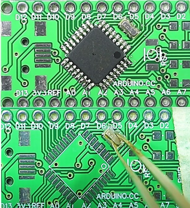
Integrated Circuits (ICs)
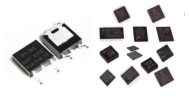
SMD is a type of chips that executes various roles in the performance of microprocessors, storage guides, and digital logic gate circuits. On a minute scale, they represent the simplest of the building blocks that form these electronic contraptions.
Inductors
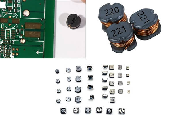
SMD inductors serve as stores for the energy which is deposited into them in the form of magnetic field. Together with capacitors, the diode is used to filter or oscillate circuits.
Connectors
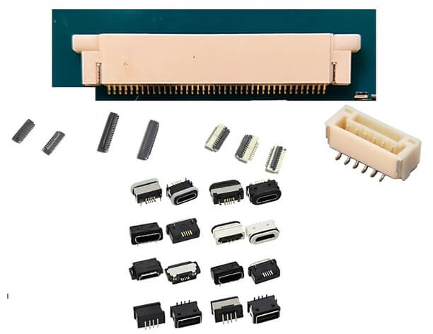
Flexible interconnects, such as surface-mount devices, are utilized to link PCBs and external electronics devices or PCBs directly. These are made in many different configurations, such as board-to-board plugs, USB connectors and HDMI connectors.
Switches
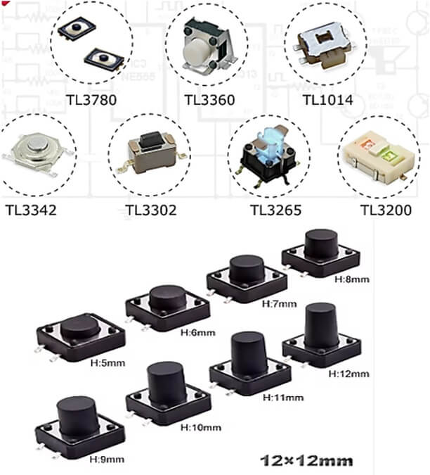
SMD switch is a device that is used to control the direction of the current flow in a circuit. Such switch can be a tactile switch, a slide switch, a rotary switch, etc..
There are three main types of SMT assembly process
You can see below the three main types of surface mount assembly:
Surface Mount Device (SMD) Assembly
This is the most frequent type of through-hole assembly, whereby electronic devices are mounted on the opposite sides of the PCB. SMD components generally are smaller and lighter than through-hole components, giving the possibility to locate a larger amount of components in a single PCB.
Chip-on-Board (COB) Assembly
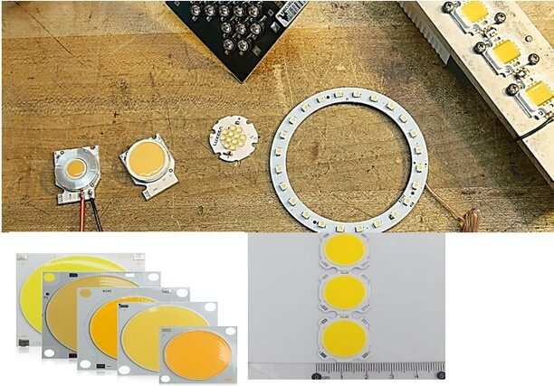
In the case of COB assembly, the led chips are directly mounted onto the PCB board and after that, they are directly bonded with copper circuits on the board. High-rise buildings that cram all sections of society are ideal for this approach, as space is less than the growing population of people.
Ball Grid Array (BGA) Assembly
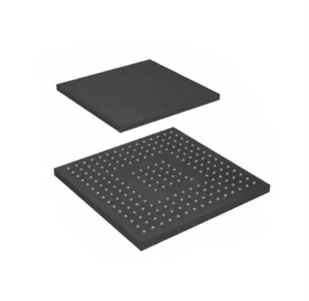
With BGA assembly, elements are positioned using joints of a solder ball array on the bottom component. Hence, solder balls are balled out and reflowed onto in order to form connection with PCB. BGA components, as their high pin counts initiate, are essential for high-reliability and superior-thermal performance applications.
Advantages and Disadvantages of surface mount components?
Advantages of Surface Mount Components:
- Size and Weight: SMDs are miniature and light-weight instead than through-hole components, so you can make more limited and compact electronic devices now.
- High Component Density: SMDs can be positioned closer than the surface mount technologies on the same PCBs, especially when considering the surface mount technology (SMT). Therefore, SMDs can significantly reduce the size of a printed circuit board (PCB) without adding any chips.
- Lower Cost: Normally, SMD assembly is cheaper than through-hole assembly. For high-volume productions, generally, SMD assembly is more cost-effective than through-hole assembly.
- Improved Electrical Performance: Such structures provide better electrical results because of shorter tracks, which leads to lower parasitic capacitance and inductance.
- Design Flexibility: SMDs make allowance for the wide availability of modern PCB designs, as components can be fitted on both sides of the board.
- Automated Assembly: SMD components are readily mounted accurately and in a short time through the use of automated insertion mount machines and pick-and-place (plant) tools, thus reducing wages and energy levels.
Disadvantages of Surface Mount Components
- Soldering Difficulty: The smaller area of SMD components makes them more difficult to solder manual assembly, which in turn requires more defined equipment with high standards of skills.
- Repair and Rework: SMD modules are very difficult to repair or replace if they are plated through holes by hand because through-hole components are easy to replace.
- Reliability Concerns: SMD parts may be sensitive to physical stress as well as thermal stress background, so they can be less reliable.
- Component Availability: One of these is that some elements may be available only in through-hole-mounted packages; thus, this will be a hindrance to the use of SMDs in specific applications.
- Initial Cost: The first costs that integrate the acceptance of SMD technology, like training and equipment costs, can be more expensive than long-term technology through-hole boards.
Surface Mount Design Considerations
- Component Selection: Consider using parts that can be tightly attached, with regard to their specifications, package type, and thermal properties.
- PCB Layout: PCB design needs to incorporate surface mounting components, taking care of gaps, geometry, and position alignment. Consequently, automated assembly will become possible.
- Solder Mask and Paste: Use one of the solder mask and solder paste application models that will be effective in the right soldering of surface mount components on the PCB.
- Thermal Management: Thermal management, for instance, thermal vias, might be necessary to avoid overheating surface mount components.
- Testing and Inspection: Adhere to the necessary testing and inspection methods so as to verify the reliability and related functionality of the surface mount assembly.
- Assembly Process: Apply automatic pickn’place devices and reflowed soldering approach for the smooth and dependable operation of component lead surface mounting.
- Component Orientation: Correctly place the surface-mount components and time the planar mounting process of the polarized components like capacitors and diodes properly for faultless assembly.
- Component Height: The height of a surface mount component is the spacing given by other components or mechanical subsystems; therefore, needs to be considered.
SMT Design For Manufacturability
Design for manufacturability (DFM), which principally is for surface mount technology (SMT boards), involves bringing PCB design so as to achieve effective and cost-efficient manufacturing processes. Key considerations include:
Component Accessibility
Make sure that the parts are setup in such a way that the placing and picking up of machines for assemblage are freely accessible.
Optimized Layout
Design the PCB so that minimum rotations by nearby components are allowed, the assembly cost is reduced and time saved.
Pad and Trace Design
With this, ensure that your reference designs use proper pad sizes and trace widths for good soldering and electrical connection integrity.
Stencil Design
Determine the best stencils to make precise solder paste deposition in the soldering process using the past drop experiment or other methods.
Assembly Test Points
incorporate inspection test points in some parts of the PCB to ensure the quality of installed components.
Clearance and Tolerance
Make sure to leave appropriate spacing and no tight tolerances to account for manufacturing irregularity, which could result in manufacturing errors.
Assembly Documentation
Offer a full assembly documentation package that contains component placement files and assembly drawings, allowing for sufficient manufacturing.
What are the comparison of characteristics between SMT and through-hole mounting?
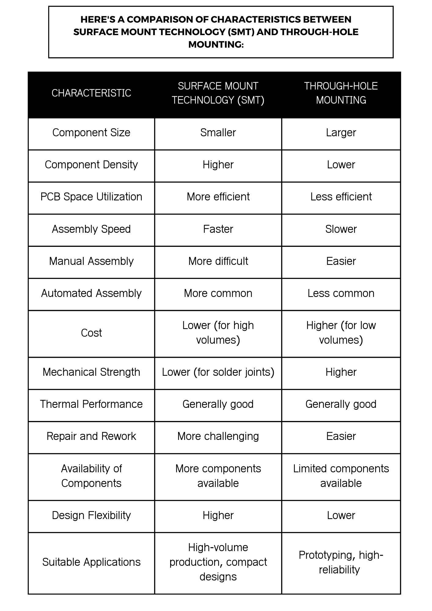
SMT (Surface Mount Technology) and THM (Through-Hole Mounting) are the two most popular techniques for assembling parts on printed circuit boards (PCBs). The methods are different from each other with regard to application-specific needs. However, each method has unique properties and merits, depending on the application priority. Here’s a comparison of their key characteristics:Here’s a comparison of their key characteristics:
- Component Size and Board Density
- SMT: Either the leads or the size of the leads are not the problem anymore, so the components will be smaller. It does this much more conveniently, saving space on the board and enabling more items in small devices.
- THM: Parts size is larger mainly due to the necessity for the leads, which must go through board’s holes. Thus, it gives the components less density and requires larger soldering boards.
- Manufacturing Speed and Cost
- SMT: Usually, this type of method is quicker and more cost-effective with regard the development as well as the placement of components, which are done by automatic pick-and-place machinery. Hole-in-plate technology utilizes both sides of the board for arraying holes of components; therefore, the space is fully utilized.
- THM: Slightly slower and often costlier due to generally more manual placement or lead soldering stages needed, especially when applied for the first prototypes or smaller series. On the other hand, OEM customization is required for a good-reliability product which is lavishly exposed to severe stress and heat, and the added cost is also preferable.
- Mechanical Strength
- SMT: Number of components has less mechanical strength than THM as the connection is done throughout its surface. Mechanical fastening can also be reinforced through the extra fasteners if there are some parts of the structure that are under stress.
- THM: Offers good mechanical work as sorts of lead of components pass through the board and solder on the opposite side; the component physically holds the board.
- Performance in High-Frequency Applications
- SMT: In most cases, as the operating frequency gets higher, this result is obtained. This is because the inductor and the capacitor of a linear amplifier are lower in inductance and capacitance, respectively, with better high-frequency performance.
- THM: It can not be as effective with high frequencies because long enough cables and loops can be like antennas and coils that distort performance.
- Ease of Repair and Modification
- SMT: Harder to fix or adjust due to the complexity of working with the very small size of the components, which are also densely arranged on the board. It is necessary to use specific tools and possess certain expertise to repair SMT parts.
- THM: Harder to repair and modify since any components that either cannot be accessed or can be replaced necessitate taking apart the device. The series of leads, electrolytic copper and through-hole construction makes it easier to manually solder and desolder components by hand.
- Reliability and Durability
- SMT: Thus, might be unreliable in extremely high-stress circumstances (especially if the devices are not suitably designed to withstand and handle such circumstances through the use of, for example, underfills).
- THM: Generally chosen for the characteristics such as resistance to physical forces,с ambient temperature , and impact, is widely used in defence and aerospace engineering.
It all depends on the demands of a particular project: it’s size, the amount of money allocated, the production date, and environmental conditions. Modern PCBs combine SMT and THM technologies in many cases, taking advantage of each method. Here, SMT connectors load most of the components, while the THM approach improves the durability of ledge-mount connections.
Differences in Assembly process
Surface Mount Technology (SMT)
Components are now placed directly on the surface-mount packages of the circuit board using the solder paste technique and a reflow soldering process. This process is usually operated by machines which handle the components and arrange them automatically and quickly.
Through-Hole Mounting
Tailored connectorized devices are hereby positioned inside of the PCB through pre-drilled holes and then soldered in their final location. This method can be performed either by hand or with the help of computer-controlled machines, but the latter, in general, is more time-consuming than in the case of SMT assembly.
Frequently Asked Questions (FAQS)
Which is better, surface mount or through-hole?
The determination whether THT or SMT is appropriate is based on the given situation. SMT outperforms the THT in terms of thru-hole designs, compact designs, and higher-volume production. On the other hand, THT assembly process may be more suitable for prototypes, repairability, and higher reliability applications.
Are surface mount components more reliable than through-hole components?
Even though both SMT and THT components are reliable, only when they are used and assembled accordingly is a guarantee they will work well. On the other hand, SMT part could be prone to mechanical stress and thermal (heat) problems.
Is surface mount technology more expensive than through-hole?
In general, the SMT can be more economical for high-stage fabrication, which is due to chain of specialized processes. Nevertheless, SMT start-up expenses may very well be more expensive than THT setup for low-volume production or prototyping.
Can through-hole components be replaced with surface mount components?
For some devices via-hole components may be substituted by SMT equivalents although this often requires unnecessary project’s design and through hole board space planning to provide an appropriate space.
Are there any limitations to using surface mount components?
Surface mount components lack power handling ability, accessibility of certain components in this type of package, and soldering technique availability.
Which technology is more commonly used in modern electronics?
SMT surface mount technology is now more commonly used in modern electronic hardware because of its low space, high component density, and automated manufacturing lines. But in spite of this, through-hole mounting technology is used in certain situations where the advantages of mechanical strength and ease of repair are of particular importance.
Conclusion
In summary, there are a number of indispensable factors that influence the decision between SMT and THT, including the production level, budget constraints, and design specifications. In addition, if any of the recycling or mechanical strength is needed, there will be restrictions to fix in this function. SMT is widely used in production with its huge throughput and modern designs by virtue of the miniaturization of the components and higher component density. THT is most definitely a match for prototypes, limited production volume infrastructure, as well as parts with higher mechanical evenness. In such instances, there are positive sides to each technique; the technology to be employed should be determined depending on the exact project vision.