Printed circuit boards should be designed and produced according to the normal PCB thickness criterion. This is an essential requirement. This paper will focus on the standard PCB thicknesses in electronics and why it matters.
What is the Standard PCB Thickness?
By the standards in the industry to standard pcb thickness, thickness of a printed circuit card (PCB) which is quite common lies somewhere between 0.062 and 0.125 inches or equal to around one point five seven mm(mm)and three point eighteen93 millionth respectively
This thickness must be preserved to ensure that the board is structurally sound and can house many components standard thickness to the pcb board thickness. When there is a space constraint, thinner boards tend to be used. Mean, thicker boards offer better resistance and can handle more current. The PCB thickness is selected based on needs of the electronic device and what it has been designed to do.
PCB Board thicknesses
One of the key aspects in electrical design is PCB thickness because it influences such considerations as flexibility, cost and performance. Available standard thickness options range from 0.6mm to 1.6 mm, where thinner boards sometimes trade precision for durability (depending on usage).
The pcb core thickness usually it is Normal thickness is between 0.6 mm to1,6 mm some can custom pcb thickness to the typical pcb thickness. Thicker boards offer better stiffness and heat dissipation for applications that require high durability. The decision depends on the specific needs of a project, including how components are laid out; manufacturing limits for positioning and quality issues with signals. To achieve the most efficient PCB functionality and reliability for a designed electronic system, designers balance these two elements.
The various levels of thickness range
The thickness levels of the PCB range from 0.6mm to 2.4 mm, and it is most common at a value gap (1–3). In applications including limited space thinner boards, which are usually less than 1.0 millimeters in thickness are used. But boards that are thicker varying between 1.6 and 2.4 millimeters offer more stiffness for applications where durability or heavier components is required The decision is based on the specific design demands and application of printed circuit board.
PCB copper thickness range
The thickness levels of the PCB range from 0.6mm to 2.4 mm, and it is most common at a value gap (1–3). In applications including limited space thinner boards, which are usually less than 1.0 millimeters in thickness are used.
You can also see the two copper layers But boards that are thicker varying between 1.6 and 2.4 millimeters offer more stiffness for applications where durability or heavier components is required The decision is based on the specific design demands and application of printed circuit board.
PCB trace thickness
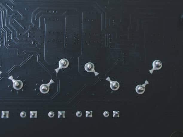
In the frame of a printed circuit board ,the designation “PCB trace thickness” means how thick conductor copper traces are. It is most frequently measured in ounces per square foot (oz/ft2-3) units. Traces such as 1 oz are suitable for general use but thicker traces like 2oz or even further,3oz with the resistive capability and strength increased to meet applications where additional durability is required or current handling requirements. The decision is defined by the specific electric and mechanical needs that are incorporated into the circuit design.
Calculating Your PCB Thickness and Layer Arrangement
Calculating PCB thickness involves considering the layers and materials used. Standard PCBs often have a core layer with copper on both sides some may have a substrate layer, copper Clas material and insulating material to the fabrication of the PCB Fabrication such as to the substrate material, nominal thickness to the design and manufacturing factors to the inner layer of the multilayer board. Here’s a simplified approach:
1. Core thicknesses
The first step will be the thicknesses of core layers, which are usually presented in millimeters. This may be the first layer of insulation that has materials like FR-4.
2. Copper thickness of the board
Add the thickness of copper layers present for both sides. The most popular ones are one ounce (0.035mm), two ounces (0. This increases the overall thickness of PCB also the copper tracks.
3. Prepreg thickness
Consider the thickness of prepreg layers that can be sandwiched between core and copper layer if your PCB bears additional layers (more than double-layer board) which is to the top and bottom layers to the internal thicknesses to laminate material into the ege connectors. Prepreg, a layer of resin-saturated fiberglass needed to help the relationship between core and copper.
4. Finished printed circuit board thickness
Finally, the thickness of any surface finish such as HASL, ENIG or OSP should be factored in. This layer is normally rather thin but contributes to the total thickness.
First, make sure that the thickness you have obtained is consistent with design requirements considering elements such as mechanical strength signal integrity and manufacturing limitations.
Design Factors that Impact PCB Thickness refers
Additionally, you are able to see the many design aspects that play a role in determining the pcb thickness that you choose.
1. Mechanical Strength
The use of thicker printed circuit boards (PCBs) provides increased mechanical robustness, which is essential for applications that are exposed to significant vibration or physical stress.
2. Current Carrying Capacity
Thicker copper traces and layers are capable of withstanding larger current loads, which makes them suitable for use in circuits that demand growing power supply.
3. Impedance Control
One of the reasons for achieving acceptable impedance values in RF and high-speed digital applications is PCB thickness. Some trace thicknesses may be required to achieve controlled impedance.
4. Thermal Considerations
Thick boards may more efficiently dissipate the heat. In the case of applications such as power electronics and where heat dissipation plays a significant role, it is an important factor.
5. Space Constraints
For space-saving designs, smaller printed circuit boards (PCB) might be necessary. Alternatively, larger and more sturdy applications might enjoy the improved lifespan offered by thicker boards.
6. Cost and Manufacturing Constraints
Thicker boards may be associated with higher material prices that might influence production rates. Cost and performance are critical considerations during design stage.
The Manufacturing Factors that impact PCB thickness options
Some of the manufacturing parameters that can affect thickness selection along PCB printed circuit boards include It is important to note that:
1. Material Compatibility:
PCBs can be made of various materials like FR-4, polyimide, and flexible circuits. There is a range of thickness for every material, which should be compatible with the selected manufacturing process.
2. Design Complexity
Some of the more complicated PCB designs that have multiple layers, components and a significant amount of circuitry can be constructed using boards which are thicker to ensure proper functioning. The total thickness can be affected by the number of signal layers, power planes and ground planes.
3. Component Height
Height of electronic components, such as surface-mount devices (SMDs) and through hole type may determine an appropriate minimum thickness option. If the components are too high, thicker boards may be required to avoid interference or damaged board.
4. Manufacturing Processing thicker copper
Various PCB manufacturing methods like etching, lamination and soldering can have an impact on the available thickness options. Some processes may be limited by equipment capability or process control, as in the case of board thickness.
5. Electrical Characteristics
Certain applications might need special electrical features, that is; controlled impedance or high frequency performance. These properties may be achieved when adding new layers or particular dielectric materials that influence the resulting thickness.
6. Thermal Management
Thermal factors are critical in PCB design. In the event that a circuit generates considerable heat or demands high dissipation, thicker boards with advanced thermal management methods such as heatsinks or thermal vias may be needed.
7. Cost Considerations
Thicker PCBs generally involve increased material consumption, longer manufacturing lead times and may entail additional process steps. Such issues affect the whole cost of production, so costs may make a range for PCB thickness.
Why is the PCB Copper Thickness Unit in Ounces?
The thickness of printed circuit board (PCB) copper is measured in ounces per square foot unit which came from the methods used traditionally within electronics industry. Such conventions, dating back to the early years of printed circuit board manufacturing have simplified communication and standardization.
During the specification of copper’s thickness, ounces provide a fundamental standard to estimate how much layer is applied per square feet that are used on the board’s surface. This widespread unit is an ally of designers, manufacturers and suppliers in the industry because it facilitates discussions between people that are clear and coherent while they exchange information.
More Details about PCB Copper Thickness of the board thickness
The PCB copper thickness value is defined in ounces per square foot (oz/ft2), which stems from the traditional methodologies of measurement that have been utilized within this electronics industry.
This and other conventions greatly facilitate communication as well as standardization, both of which were introduced in the early ages associated with printed circuit board manufacturing. In specifying the thickness of copper, using ounces provides a simple idea of how much coated area is applied to one square foot.
This is achieved during the process of determining copper thickness. In doing so, this standard unit makes the negotiations clear and consistent even among designers, producers as well as suppliers operating in the same industry when they are engaging one another.
Other Factors Affecting PCB Thickness options
Not only the amount of copper thickness but also, several other parameters affect selection of total PCB thickness. An important consideration is mechanical strength.
Thicker boards offer higher resistance when it comes to durability and hence, they are ideal for applications that involve vibration or physical stress. Besides the carrying capacity of the copper, even overall board thickness influences current. Some requirements for specific thicknesses may be dictated by the need to satisfy impedance type traces regulated in high-speed digital and radio frequency cases.
Moreover, there are thermal considerations; thicker boards distribute heat better which is relevant for higher heat demanding apps.
To reach an ideal PCB thickness that is conducive to the unique requirements of their potential application, designers should find a middle ground between these characteristics as well as space limits and manufacturing concerns.
Standard Two-Layer PCB Thickness of the board
While calculating the required thickness of a two-layer printed circuit board (PCB), there are several things to consider. In most cases, copper layers are on both sides of the board that consists a central material often FR-4.
The core may be as thick from 0.6mm up to a maximum thickness of 1.6 mm . It is one of common practices to specify copper layers in ounces per square foot (oz/ft2), including most frequently used choices:1 oz and 2 oz.
Consequently, an ordinary two-layer PCB may have a core height of up to1.6mm in addition to the copper thickness on both sides that could either be 1oz or2 oz.
Here, to maintain an equilibrium among several design parameters such as mechanical stability of the entire assembly current – carrying capacity and overall reliability this thickness is a necessary parameter.
Four-Layer PCB Thickness Standard
The combination of many layers and materials is required to achieve the typical thickness of a four-layer printed circuit board (PCB). A core layer, two inner copper layers, and outside copper layers are the components that make up a standard configuration design.
The thickness of the core, which is typically comprised of FR-4 material, may vary anywhere from 0.8mm to 1.6mm. It is typical practice to choose between 1 ounce and 2 ounces for each copper layer, which is measured in ounces per square foot (oz/ft2).
The core thickness and twice the thickness of one copper layer are added together to get the overall thickness of the four-layer printed circuit board (PCB). Providing a balance between signal integrity, thermal concerns, and manufacturing restrictions, this design satisfies the electrical and mechanical needs of the circuit. It also provides protection against thermal interference.
What Affects a PCB’s Thickness?
Printed circuit boards (PCBs) have a thickness that is determined by a number of different variables. When it comes to the ideal mechanical strength, thicker boards give better durability and resistance to physical stress or vibration.
This is one of the key factors to consider. There is a correlation between the thickness of copper layers and the current-carrying capacity of the material. A higher thickness allows for a better ability to accommodate electrical currents.
When designing circuit boards for applications that have specified impedance requirements, the choice of PCB thickness is very important for attaining regulated impedance traces. In addition, thermal concerns are important, since boards that are thicker have the ability to disperse heat more efficiently, which may have an influence on performance in conditions with high temperatures.
The decision on the thickness of the printed circuit board (PCB) is a complicated design option that effects the board’s functionality and dependability. Additionally, manufacturing restrictions, space limits, and cost considerations all contribute to the overall decision.
Conclusion
In order to comply with certain design principles, various different issues must be considered so that the standard PCB thickness specifications can be understood. No matter whether the printed circuit board is two layers or four, the selection of core materials and copper thickness as well as overall board height are highly relevant.
Designers must pay a great deal of attention to such important factors like mechanical strength, current-carrying capability, impedance management and thermal effects during the production engineering design. Communication across the sector is facilitated by uniformity of measures and standard use of ounces per square foot industrywide.
All in all, making an informed decision on the thickness of printed circuit board (PCB) ensures a perfect performance, reliability and cost effectiveness for PCB deployed to its intended application.