Learn about the different processes that are involved in manufacturing multilayer PCB to the multilayer PCB manufacturing process either outer layers. In the context of developing multi-layer printed circuit boards, research on advantages disadvantages and applications of advanced types will be required you can also reaf the advantages of multilayer pcbs. The multilayer printed circuit board (PCB) fabrication method is one of the most critical aspects in manufacturing high quality electronic circuits for multilayered PCB’s. This article aims to increase the knowledge of PCB designers and manufacturers on all processes involved in the manufacture multilayer printed circuit boards (PCBS).
Overview of multilayer pcbs
Multilayer PCBs, or multilayered printed circuit boards, constitute an advanced development in electronic circuits design and manufacturing some have multiple single layer pcbs and multilayered pcbs to the inner layer core or outer layers, copper layer. Unlike single-layer or double-layer PCBs, multilayer PCBs have multiple layers of conductive material between insulating materials that form a three dimensional circuit structure to the double sided boards some which have at least three layers to the double layered pcbs some in the woven glass cloth. These designs have a higher component and interconnection density, so they are an essential part of complex electronic systems.
Here are key aspects of multilayer PCBs:
- Layered Structure: Multilayer PCBs are made up of three or more layers conductive paths between insulating materials. Lamination of the layers gives a compact design that functions well.
- Increased Component Density: The extra layers enable greater component density than single or double-layer PCBs. This is critical in the case of modern electronic devices that require both functionality and space within a limited area.
- Improved Signal Integrity: Multilayer PCBs are superior in signal integrity because they have various layers that can act as power and ground planes. This facilitates the prevention of EMI and crosstalk between traces for improved circuit functionality.
- Complex Circuitry: For such complicated circuits with multiple layers and difficult connections of components, multilayer printed circuit boards are employed. The circuit layers allow for a more efficient trace routing, which in turn reduces signal delays and ensures better performance.
- Thermal Management: The extra layers are also helpful in thermal control. Using multiple layers allows for the distribution and dissipation of heat from electronic components more effectively, eliminating overheating issues at the same time.
- Applications: The advanced electronic devices that use multilayer PCBs include smartphones, tablets, computers, medical equipment and automotive systems. They are irreplaceable in areas where such characteristics as space, performance and reliability need to be taken into consideration.
- Manufacturing Challenges: Manufacturing of multilayer PCBs, in comparison to single or double layer boards is a more complicated process. It features highly elaborate and expensive operations including precise alignment, lamination, as well as drilling.
Lastly, multilayer PCBs are a vital element in the advancement of electronic technology that offers vast space for creating sophisticated and effective circuits. The demand for smaller and more powerful electronics will also undoubtedly help to create new innovations in multilayer PCB design as technology progresses further.
What is a multilayer printed circuit boards
A multilayer printed circuit board (PCB) is an advanced electronic component that has several layers including the conducting material and insulating substrate. On the other hand, MCUs utilize a number of copper tracks which are separated by insulating materials. Such boards are specifically created to handle intricate and condensed circuits, which possess benefits in terms of increased functionality, portability as well superior signal quality.
In building a multilayer PCB, this is usually done by alternating layers of conductive copper and insulating material which can be epoxy resin with fiberglass. The vias, which are tiny holes filled with conducting material, connect different layers and allow electricity to move from one layer to another seamlessly.
All types of electronic systems including consumer electronics (smartphone, computers), industrial, and automotive utilize multilayer PCBs. These functions include the capacity of such phosphor bronze to maintain complex circuit layouts, minimize electromagnetic interference and efficiently utilize space in electronic manufacturing industry.
How do the multilayer pcbs manufacturing process work?
Manufacturing of multilayer PCBs involves several complicated steps that are used to achieve sophisticated electronic circuits. First, a substrate material such as fiberglass-reinforced epoxy is coppered on both sides to create a thin film. The holes are drilled to enable interconnection of circuits.
Electroless copper deposition is a process that occurs after drilling and creates conductive pathways by adding a thin layer of copper to the walls. Second, to define the circuit pattern, a layer of photosensitive material known as photoresist is applied and selectively exposed to UV light through a photographic mask.
Unwanted copper is thus removed by chemical etching, and only the necessary traces remain. This cycle is repeated for each layer and insulating layers, usually pre-impregnated fiberglass epoxy, are interleaved with conductive layers. After all the layers are done, these individual sheets are stacked up and pressed under heat and pressure to produce a solid multilayer PCB.
Lastly, the board receives surface finish and solder mask as a way of protecting its appearance capability. This detail-oriented process results in the production of high quality and complicated multilayer PCBs that are used on numerous devices.
What is a pcb manufacturers via?
A “via” is an integral part of the PCB boards manufacturing process, as it serves to ease out electrical connection establishment across different layers in a printed circuit board (PCB). The word “via” means an insignificant hole that is drilled through the board and then metallized to create a conductive path between layers. A few variants of vias can be found, such as the blind/buried and through-hole vias. Although blind vias are limited to link an exterior layer or two inner layers, through-hole vias cross the entire width of a printed circuit board (PCB) and connect all its layers.
On the contrary, buried vias are only between the inner layers. Creating vias starts with drilling holes into the substrate. Later, an inner conductive layer is applied to the inside of a hole through techniques including electroplating or chemical deposition. Without the help of vias, it is not possible to come up with circuit designs that are intricate and compact. Vias allow signals and power to span the many layers of a multilayer PCB; in turn, this gives access to all sorts of circuit characteristics.
Factors while building the multilayer pcbs
To achieve maximum performance, reliability and manufacturability the construction of multilayer printed circuit boards (PCB) needs to be approached with consideration for a diversity of aspects. Important considerations to keep in mind throughout the design and production of multilayer printed circuit boards are as follows:
1. Layer Count:
Depending on the complexity of a circuit and how much space there is, one should choose the number of layers required. However, more layers result in an increase of routing options though also elevating the procedure complexity and cost.
2. Layer Stackup:
The layer stackup should be explained as the layout of insulating substrate and copper layers. Consider the density of each layer and material’s characteristics.
3. Signal Integrity:
Focus on such considerations as the integrity of signal, primarily related not only to impedance control but also to crosstalk and electromagnetic interference (EMI). Some of these challenges can be mitigated by applying the appropriate layer stackup and routing techniques.
4. Power Distribution:
Build an effective power distribution network for the printed circuit board to have a consistent and uniform supply of energy. Consider the architecture of power and ground layers of the aircraft and place ground plane carefully together with powered ones.
5. Via Types:
Identify, considering the design requirements and cost consideration factors which vias are acceptable as through-hole via blind or buried. Consider the impact of vias on signal transmission or signal integrity.
6. Routing and Trace Density:
Minimize the routing of traces to reduce pcb manufacturers size and control the path count. Density and spacing of the traces can be considered to prevent electrical connections or electrical interference.
7. Thermal Considerations:
E Perform an analysis of the thermal management requirements, focusing on high temperature electrical connections elements. You should consider using the thermal vias, heated hydraulic press or heat sinks or more than two layers cooling solutions in order to ensure proper dissipation of the heat.
8. Material Selection:
Identify the appropriate substrate materials based on their dielectric constant, thermal conductivity and mechanical strength. The material used also may affect the overall performance and signal integrity.
9. Manufacturability:
When designing, remember to consider the possibility of manufacturing multilayer pcbs. In addition to the pcb manufacturing method that you have chosen, consider it’s capabilities and ensure compatibility with equipment commonly used by manufacturing process.
10. Cost Constraints:
Remember the budget limitations and implement it in a manner that is cost-effective. The number of layers, the materials used and weaving will be considered as variables.
11. Testing and Inspection:
Develop a testing and inspection plan that would be used in the production of produce multilayer pcbs. Consider test points and the testing needs of printed circuit board manufacturing process.
12. Compliance and Standards:
There is a need for the design of multilayer PCBs board to follow all industry standards and regulations. All environmental compliance, safety regulations and any other standards should be considered.
13. EMC/EMI Compliance:
Solve electromagnetic compatibility and interference issues with appropriate ground plane methods, shielding techniques along with those layer core materials.
Through pondering over these components, designs are able to design multilayer pcbs that not only perform adequately but also prove operative in performance and can be produced successfully while keeping an eye on the budget. Other things that contribute to the success of multilayer pcbs are working with professional PCB manufacturers and adopting good practices in all industries.
Applications of multilayer pcbs
Many industries use multilayer printed circuit boards (PCBs) because they have a number of advantages such as compact design, improved performance and signal integrity. In the field of consumer electronics, such as smartphones tablets and laptops multi-layer PCBs enable integration of advanced circuitry in limited space which leads to manufacture slim stylish yet powerful devices.
In the telecommunication industry, multilayer PCBs make it possible to develop sophisticated networking hardware that enables effective signal processing and data transmission. Multilayer PCBs are applied in automotive due to their ability of resisting adverse conditions and allowing for integration intricate electronic systems that enhance vehicle performance as well as safety.
However, in industrial environments these PCBs are highly valued due to the automation and control systems where space saving circuitry is essential. Aerospace devices utilize multilayer PCBs as well to create lightweight yet sturdy electronic systems for aircraft and spacecraft. These PCBs are used in the medical industry where they facilitate accurate, miniaturized devices for diagnostics, imaging and patient monitoring.
In conclusion, the flexibility and reliability of multilayer PCBs are critical in many applications that continue developing towards innovation.
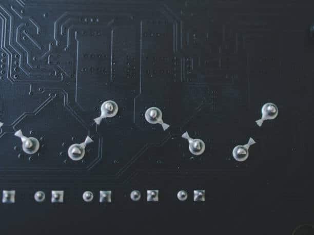
Incorrect of Accumulation of layers of conductive material
Incorrect accumulation of layers of conductive material in printed circuit boards (PCBs) can cause significant manufacturing and performance problems. This misalignment or incorrect layer stacking can lead to electrical short circuits, signal interference and ultimately complete failure of functionality. The conductive layers, often copper ones, require accurate alignment in order to create the desired circuit routes.
Incorrect accumulation can also lead to problems during the drilling process of vias, which impacts connectivity between various layers. In addition, it may affect the structural strength of the PCB and reduce its reliability in future. Quality control measures for the manufactures should be very strict so that incorrect layer accumulation can be prevented and PCB will function properly in electronic devices.
Layers of multilayer pcbs
Multilayer printed circuit boards (PCBs) are made up of several layers that play individual roles in the overall functioning of an electronic device. The fundamental components are conductive layers and insulating layers. The conductive layers, which are usually copper-based, serve as the basis for building electrical paths and connecting different elements. In between these conductive layers are insulating substrates, usually made of materials such as fiberglass-reinforced epoxy resins.
The number of layers in a multilayer PCB depends on the intricacy of the circuit and design requirements. The stackup of these layers is one key factor that influences the performance, signal integrity and overall reliability of a PCB. Other layers can be included for specialized purposes, including ground planes, power planes and signal layers. As a whole, these layers allow for the development of sophisticated yet small and efficient electronic circuits in three-dimensional space; thus multilayer PCBs are an essential part of modern electronics.
Where should the electronic components be mounted?
The electronic components are positioned on PCBs according to the function, number of signal flows and spatial optimization. The location of the components is one of the most important elements in PCB design, and it affects performance as a whole. Signal path lengths are minimized, interference is reduced and heat dissipation efficiency increased by the components’ arrangement.
The integrated circuits, connectors and critical components are usually located closer to the center of a PCB in order to minimize traces while ensuring signal integrity. Power-hungry elements can be placed in a way that allows for effective heat management. The selection of component placement is informed by design principles that strive for a compromise between electrical performance, thermal issues and manufacturing requirements resulting in reliability as well as functionality within the electronic system.
What is the purpose of a multilayer PCB?
The main function of the multilayer PCB is to allow complicated electronic circuits manufacturing in a small and efficient manner. In contrast to single-layer PCBs, which suffer from spatial and routing constraints, multilayer PCBs are made of several layers that involve conductive traces on a dielectric substrate. This enables highly complex circuit designs with increased functionality, better signal integrity and greater component packing. Multilayer PCBs are especially important in the modern electronics industry, where miniaturization and effective use of space play a crucial role. The applications encompass a broad spectrum of electronic devices such as smartphones, computers, medical equipment and automotive systems that pave the way for sophisticated technologies by offering an immovable ground to integrate various components with different functionalities.
The benefits of multilayer boards
The advantages that multilayer PCBs offer have made them an indispensable element in the electronics sector. Their major advantage is that much more complex circuitry can be contained in a small space, this trend towards miniaturization helps to make smaller and better electronic devices. In multilayer PCBs, there are several sheets of conductive and insulating substrates that increase the signal integrity by eliminating electromagnetic interference as it allows more options concerning components’ placement.
This improves the performance and reliability of electronic systems. Second, multilayer boards allow for higher component densities that enable more electronic components to be accommodated. This also boosts effective power distribution and enhanced thermal management with a higher layer count.
Overall, the benefits of multilayer PCBs promote technological advances as various industries are able to manufacture intricate and high-quality electronic hardware.
Suitable Surface Finishes for Multilayer PCBs
In selecting surface finishes for multilayer printed circuit boards (PCBs), the performance, reliability and longevity of these devices are determined. Other options are Immersion Gold (ENIG) which offers superior solderability and corrosion resistance for use in advanced multilayer circuits. HASL (Hot Air Solder Leveling) is one of the most widely used solutions, an affordable method that guarantees uniform coating and performs well with multilayer constructions. Organic Solderability Preservatives (OSP) is a surface finish that offers smoothness and ecology.
Moreover, ENIPIG (Electroless Nickel Immersion Palladium Immersion Gold) is becoming more popular due to improved durability and suitability with multilayer PCBs. The selected surface finish is based on the application, budget and specific requirements of a multilayer PCB design. Every surface finish option has its own set of benefits, and careful attention is necessary to address the specific requirements for a given electronic application.
Suitable Laminates for Multilayer Boards
While choosing proper laminates is one of the crucial decisions in designing multilayer printed circuit boards (PCBs), factors such as electrical performance, thermal stability and overall reliability are affected by this choice. The FR-4 laminate, which is flame retardant in nature and widely used due to its cost effective price tag while being a good insulator of electricity as well mechanical strength. High-Tg laminates are suitable for high temperature environments, giving better stability. Rogers laminates are suitable for high-frequency applications that have excellent signal integrity.
Polyimide laminates used for their flexibility and thermal stability are suitable in circumstances where the PCB must endure high temperatures or show some flex. Specialized materials such as Isola FR408 and Nelco/Megtron laminates are used to meet certain requirements for enhanced electrical and thermal characteristics, hence suitable in high-speed or high frequency applications. The selection of laminate is customized to the specific needs of multilayer PCBs, which provide an adequate compromise between performance costs and application-specific claims.
Why Choose Pure PCB as your Multilayer PCB Supplier?
The benefits of selecting Pure PCB as a multilayer supplier outweigh many other companies in the competitive market. Pure PCB is renowned for the consistency of quality and reliability that it has maintained. They follow strict manufacturing standards and use innovative technology to manufacture multilayer PCBs with high accuracy levels.
Through the customer satisfaction as its primary objective, Pure PCB has been able to ensure there is timely delivery and keeping open lines of communication during production. Their staff of highly knowledgeable engineers and technicians has vast experience in the PCB industry, which helps them to satisfy even the most strict specifications or requirements.
In addition to this, Pure PCB promotes environmental sustainability as it integrates ecological aspects into its manufacturing activities. Selecting Pure PCB as your multilayer supplier ensures you have an ally committed to providing high quality products, on-time delivery and environmentally sustainable solutions which will go a long way in ensuring success of the electronic projects.
The connection between the various levels
The interconnection between the different levels on a multilayer PCB is achieved by means of via and trace network. In particular, vias or small holes that carry current serve as the conduit for connections between different levels of PCB. Through-hole vias connect top and bottom of the board thus providing an uninterrupted path between conductive traces on separate levels.
Furthermore, blind vias link an outer layer to one or more inner layers without crossing the board’s entire thickness. Buried vias, which are inside the inner layers of a PCB and provide connections that can not be seen from the outer surfaces. The complex placement of these vias along with planned routed traces allow for a solid three dimensional circuit structure. This connectivity is crucial for signal, power and data to flow smoothly through the multilayer PCB so as to support complex electronic devices that work.
Software for creating multilayer PCBs
In designing multilayer printed circuit boards (PCBs), designers typically use software tools such as Altium Designer, KiCad Eagle by Autodesk OrCAD PADS Mentor Graphics DipTrace Allegro PCB Designer EasyEDA. These software solutions offer a variety of features for
schematic design, layout, and routing that support different levels of complexity in the designs. The selection of software is determined by the preference, project specifications and financial constraints while each tool has its distinctive features regarding functionality, user-friendliness and community backing.
Conclusion
In summary, multilayer pcb manufacturing processes are critical in the electronics industry as they allow producing small and powerful electronic devices some have double sided pcbs. The complicated method involves layer stacking, accurate drilling, conductive layer deposition and lamination which results in a 3D board with several layers of interconnected circuits. Technological and material advances ensure better signal integrity, lower EMI levels, as well as higher overall reliability. Designers can enjoy the freedom to design more complicated circuit layouts, saving space and arranging components. New innovations in multi-layer PCB fabrication techniques will continue to change the face of electronic design and manufacturing, pushing for further advancements with what can be done regarding modern electronics.