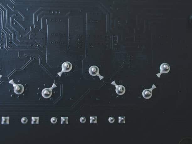
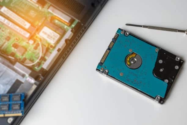
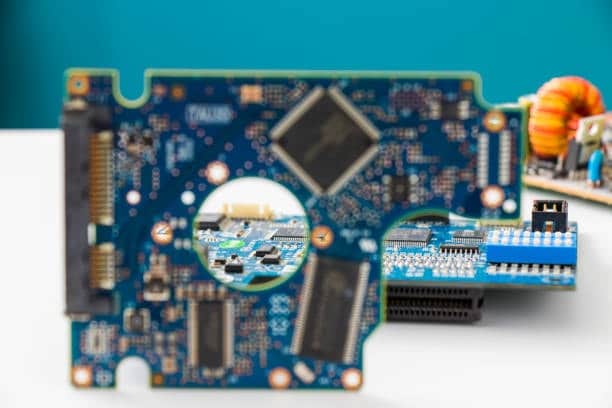
Assembling printed circuit boards (PCBs) with powerful electronics such as resistors, capacitors, and transistors is an example of one of the most common skills that every person in the field of electronics has to learn the hard way. Whatever your status, whether a serious hobbyist, a student or an experienced professional, soldering is the core skill of electronics and delivers success in projects greater than have been previously attained.
This article is dedicated to the description of handy and effective solder PCB techniques, tips and tricks which will help you solder PCBs more successfully.
What is PCB soldering?
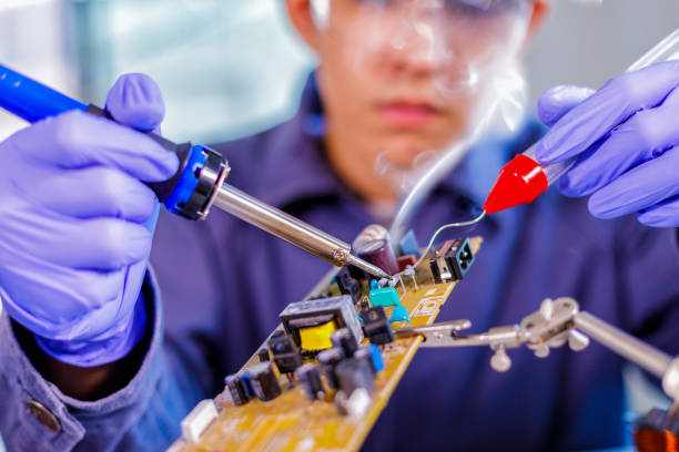
Soldering is connecting two or more components of the electronic devices by melting solder or solder melts and flowing of the solder into the joint in between. While thinking about the solder, important features of strong electrical circuits and mechanical connections between the components and the PCB are easily formed. Knowledge about the types of solder wick (leaded and lead-free), soldering irons, and flux is extremely vital because these are the components that play important roles throughout soldering iron stand.
Soldering Techniques
The soldering practices have gone through many changes with time and in response to technology and componentization revolution within the electronics. Here are some modern soldering techniques, along with the latest information:
1. Reflow Soldering
- Common in many surface mount technology applications (SMT), including soldering of small components such as resistors, capacitors, and integrated circuits.
- The process consists of such steps as the development of solder paste, positioning of components on printed circuit board, and heating of assembly or heat transfer in the reflow oven to liquefy solder.
2. Wave Soldering
- Suitable for through-hole components and designed with mass production in mind.
- The PCB is moved onto the wave of molten solder again. They form solder joints at the pads of the PCB and component leads.
3. Selective Soldering
- A combination of waving and hand soldering techniques (i.e. a hybrid method).
- Used in what is known as multilayer PCBs, holding both through-hole and surface mount parts for soldering only when needed.
4. Hand-soldering
- Fundamental for prototyping, repairs, and small batches.
- Calls for soldering iron, soldering wires and, if needed, steady hands. Some recent developments include being able to solder for high temperatures and the invention of lead-free solder for our planet’s sustainability.
5. Laser Soldering
- The latter includes the most recent one, where the solder joint point is heated with a laser beam.
- It ensures precision in control and fewer thermal constraints on components, which makes it suitable for delicate or miniature devices.
6. Induction Soldering iron
- It takes electric fields that affect the solder joints.
- Easier and uniform heating forms thermal runs, which avoid thermal shock to the components.
Latest Information
- Lead-Free Solder:The main reasons for this are lead-containing solders’ environmental and health problems; as a result, lead-free solders are becoming the established standard. This thimble top can have a blends tin, silver, and copper.
- Low-Temperature Solders: The manufacturers are beginning to use soft tin or lead-free solder alloys with lesser or lower melting point to melted solder for the soldering in order to avoid stress on sensitive components during the soldering process.
- Flux Innovations: Continuous flux formulation progression has been the basis of improved soldering effectiveness; voids and bridging are the only problems that have been reduced.
Choosing the Right Tools and Materials
- Soldering Iron: Take in a soldering iron that is adjustable with respect to temperature. An optimal temperature range of 300°C–400°C is efficiently used in most soldering processes.
- Solder: But one of the most crucial steps is to use high-grade solder that has a rosin core. The thickness of the solder should be appropriate for the soldered component and pad sizes.
- Flux: Flux eliminates scum and imbues connectivity and electrical conductivity between the joints of two parts. It is necessary to pick flux that is able to work with your solder and PCB material.
- Soldering Station: A well-established area where at good lighting and ventilation are maintained is necessary for successful and secure soldering.
What is soft-soldering and hard-soldering?
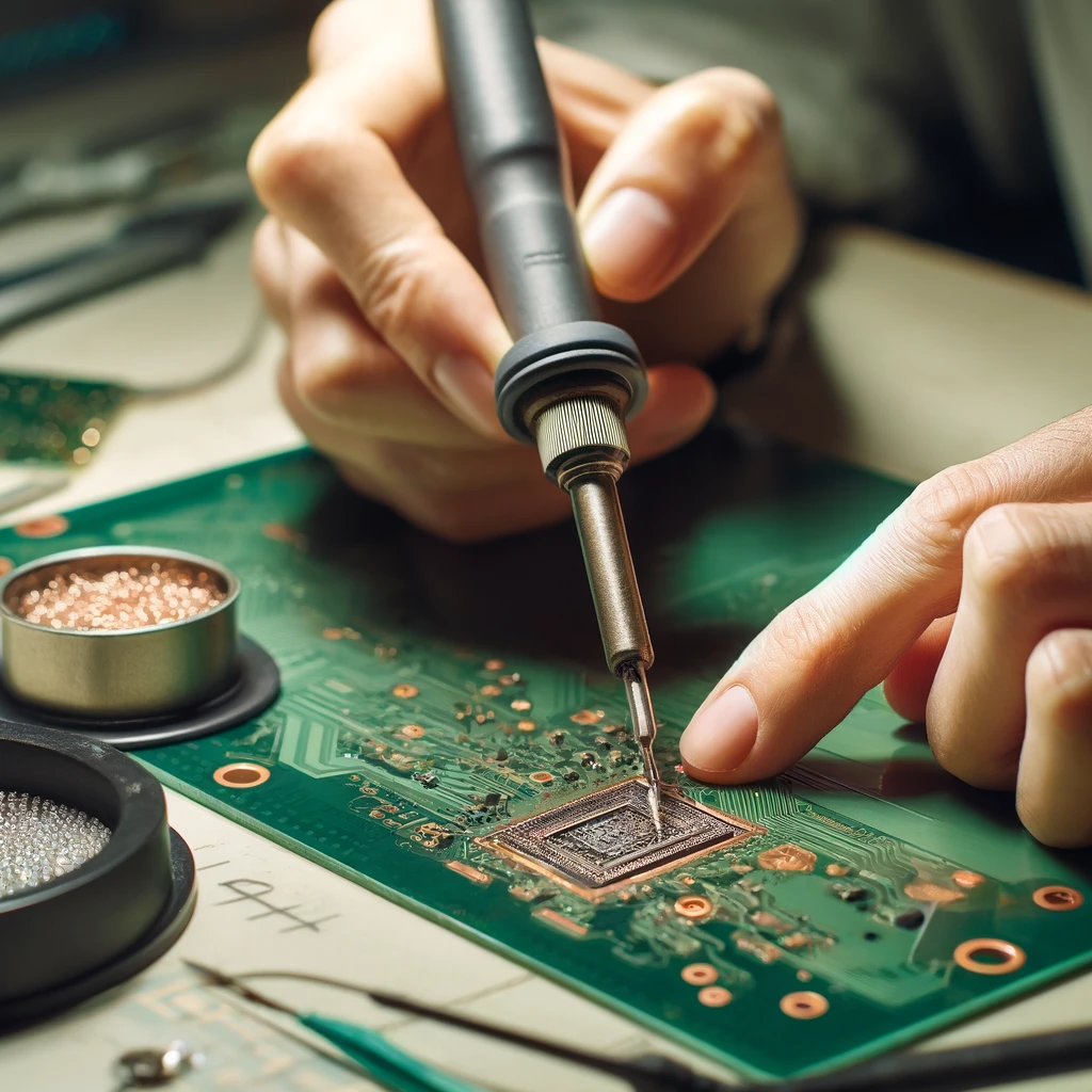
Soft Soldering: Soft soldering employs solder alloys mainly based on tin and lead, or more recently, tinned copper (soldering tin), with the aim of preventing any negative impacts on health. It is a suitable material for stiffer electrical excitation and to join sensitive assemblies in electronic devices, as it offers both high mechanical strength and superior electrical conductivity. The production process is simple and requires just a little gear, which can be used in electronics and crafts.
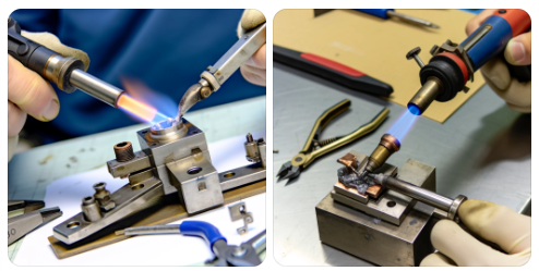
Hard Soldering: Such soldering technique engages temperatures above 450°C, and traders of these metals are brass or silver. In this way, tensiotes have been introduced into the joints, which are stronger than those made by soft soldering and can bear higher temperatures. Plumbing, HVAC systems, and metalwork applications often require welding, as much stronger joints are needed. This process employs more warmth, usually provided by a torch, and is more complicated and hard to do than soft soldering.
What are the main PCB soldering defects?
The section consists of a drawing of all the terms like cold joints, solder bridges, torching, solder balls, voiding, insufficient wetting, excess solder, oxidation, and lifted pads, which are briefly described along with the key points.
Here are some of the of the main PCB soldering defects:
- Cold Joint: Underwarming the soldering process, it can produce a weak and inconsistent connection.
- Solder Bridges: The excess solder that appears in between the pads or traces forming the open circuit.
- Tombstoning:A surface mount component was rising from one side of the PCB soldering refers; only the leading edge seemed sharp and impressive in the same way as the tombstone’s corresponding angle.
- Solder Balls: Residues of solder looking like little balls of solder were also noticeable all around the solder joint, which could cause short circuits if not removed.
- Voiding: Such spaces or regions are prone to producing air pockets or cracks, which reduce the overall strength as well as conductivity of the solder.
- Insufficient Wetting: Suffer from joints adhesion of solder to pad and lead component, indicative of weak joints.
- Excess Solder: Inadequate amount of solder or too much solder may lead to short circuits and would influence the proper functionality of the soldering circuit boards.
- Oxidation: Unlike the solder joints that oxidize or solder pins that lose the connection due to oxidation, exposing the connectors to ambient factors.
- Lifted Pads: Pads that were separated from the PCB due to excessive temperatures or when mechanical stresses pulled them away from the PCB during soldering, so remove excess solder.
It is very possible that these defects can affect the performance or operation of the PCB, and therefore, it is important to take care of them when manufacturing and assembling, especially electrical connections.
What Equipment Do You Need to Solder?
To solder, you typically need the following equipment:
Soldering Iron: A welding tool with a soldering tip that reaches a high temperature solder-melts to hot iron.
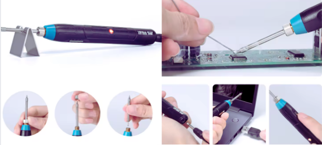
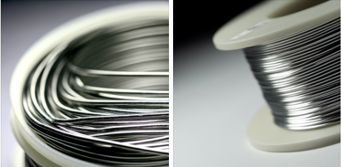
Solder: Metal alloy which at a temperature of melting and pouring pruners to a joint. The soldering material is mostly made of tin or lead, or alternative filler metal components.
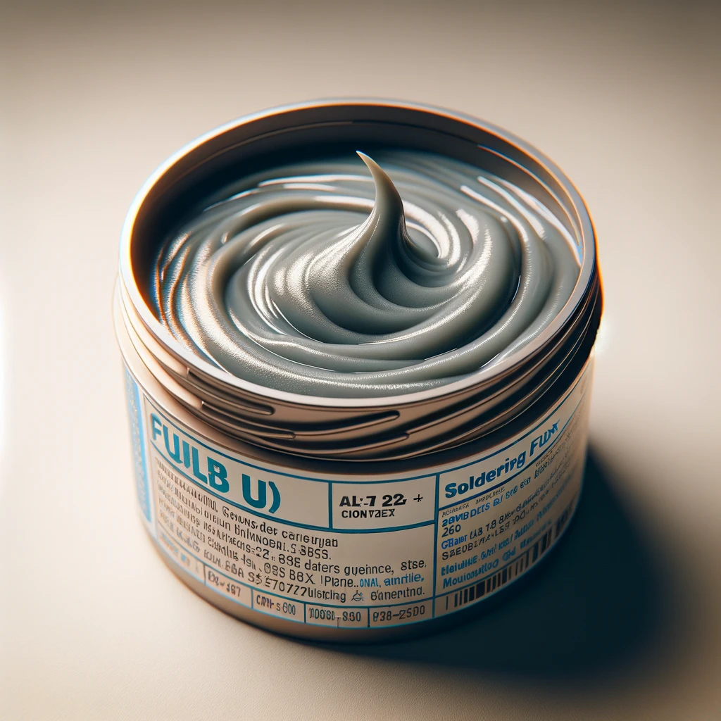
Flux: the liquid that is used to clean and prepare the surface thoroughly for soldering purposes( ionize). As you know, the preliminary preparations in soldering, such as the choice of excess flux and their application and function in terms of cleaning and preparing the surfaces,.
Soldering Stand: A holder for a soldering iron for that period when it is not being used. The setup of the soldering stand entails the components, namely the base holder and sponge area, respectively.
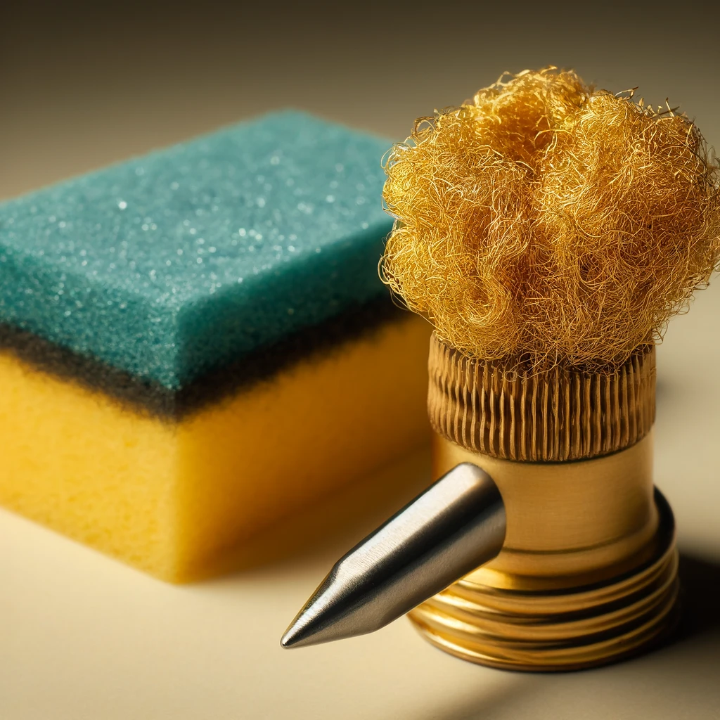
Cleaning Sponge or Brass Wool: This is improvised for cleaning the soldering iron tip, too. The baffling of both the bead-shape and long-fibre of them makes the pair appear ideal for the purpose of wiping the soldering iron tip.
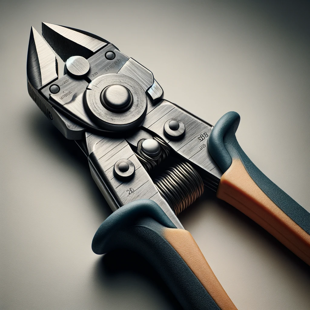
Wire Cutter: For cutting and peeling most lead or wire materials. The main parts of the solder wire cutting soldering tools consist of the handle, blades of cutting, and pivot point.
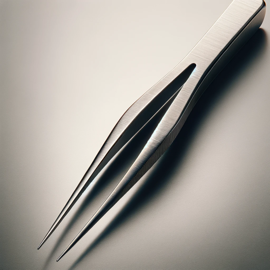
Tweezers: Use them for the sale of screws and washers where the small components have to be held steady.
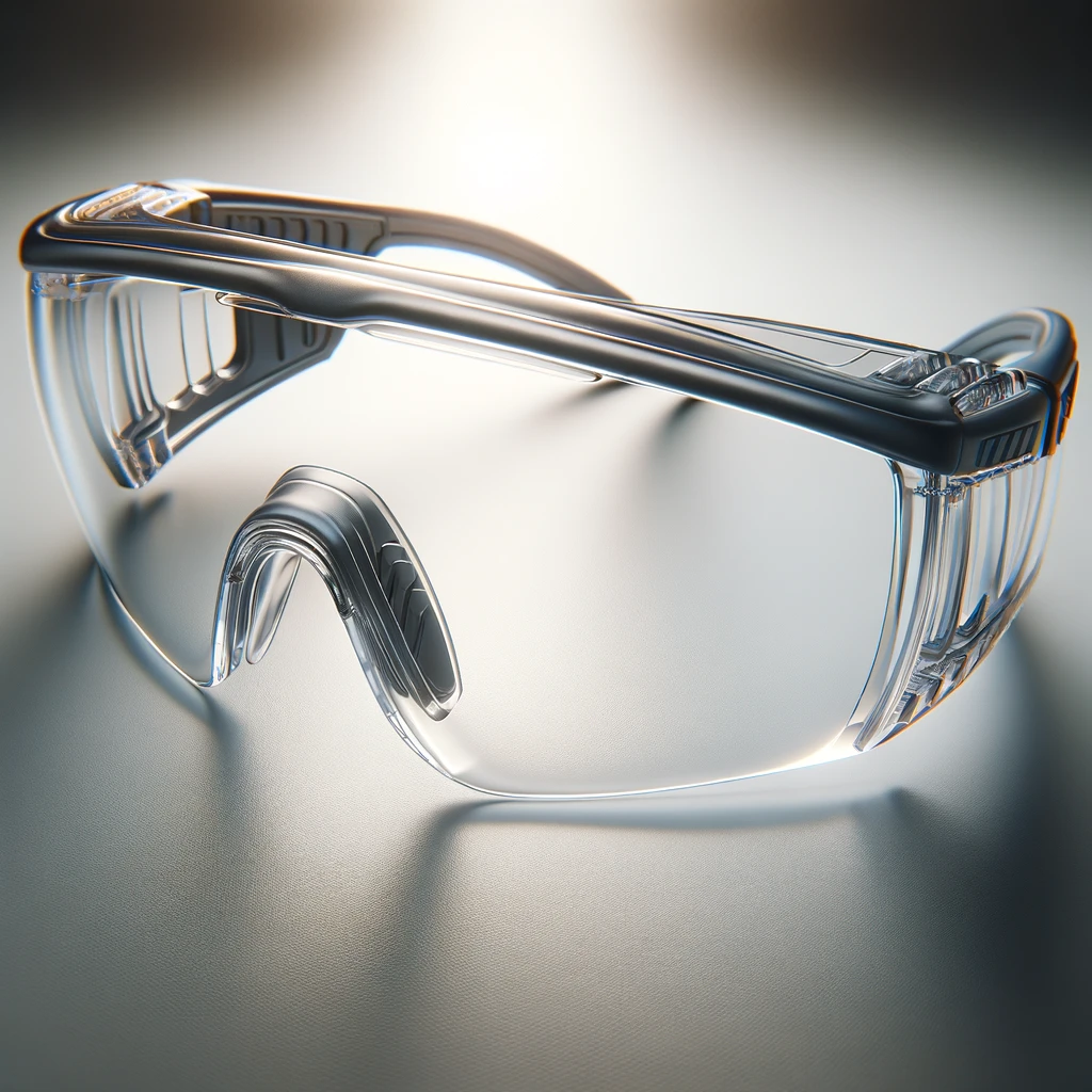
Safety Glasses: Make sure that you are wearing suitable protective eyewear against splashes and fumes.
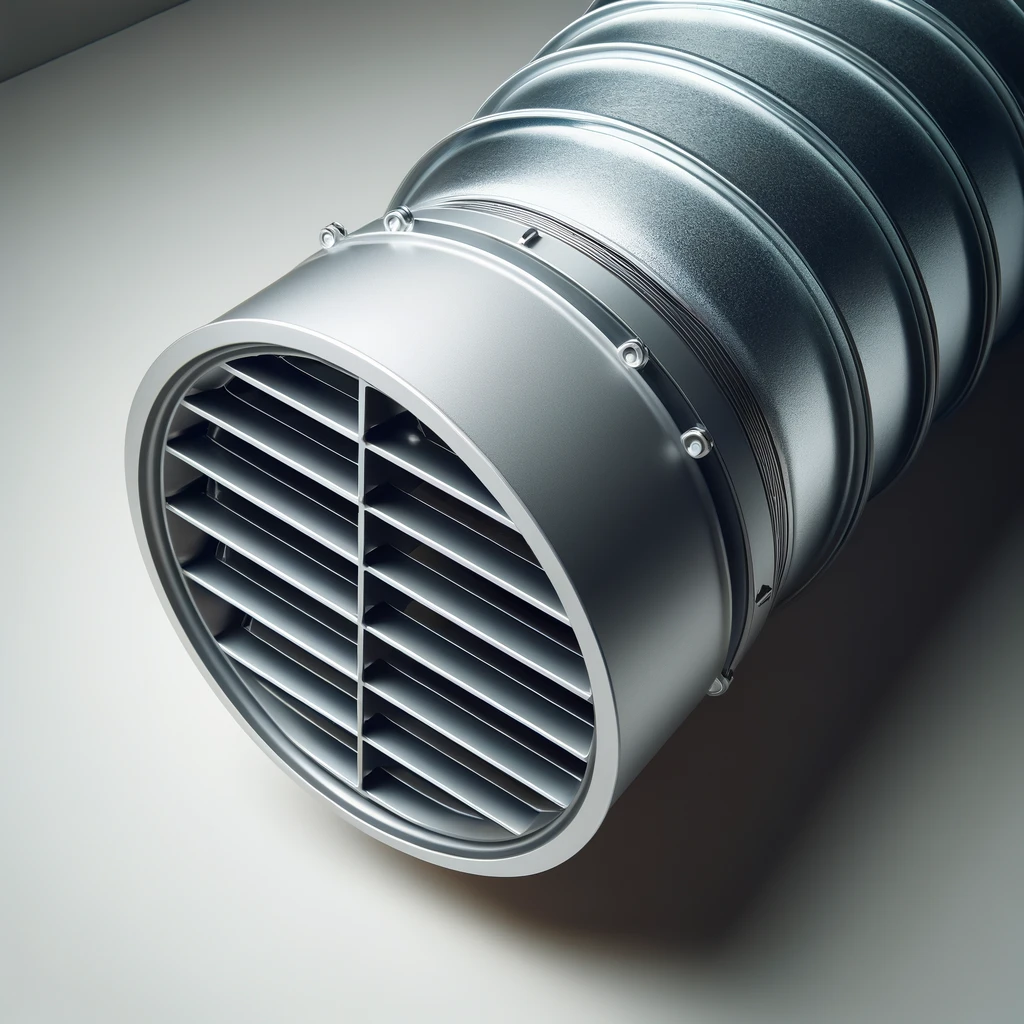
Ventilation: A fan or extractor to move off the poisonous fumes from the warehouse outdoors.
The type of soldering task under consideration may require the use of an extra tool like a desoldering pump and magnifying glass in addition to the soldering iron or heat gun.
Liquid flux is Essential for Soldering pcb
Liquid flux is an important component in soldering because it deeply cleans the solder joint surfaces and the conductive tracks (PCB), neutralizes the oxidation and increases the flow of the solder-cooled material. In this way, the boards are built out of solid and stable solder bonds that are less likely to have issues, including a cold joint or solder bridge.
Preparation and Safety for Soldering process
In terms of preparation and safety for soldering, the latest information and best practices include:
Preparation:
- Workspace Setup: Try a class of conductors—say, an ESD (Electrostatic Discharge) safe mat or surface—that does not build up static electrical component charges that would otherwise damage the components.
- Tool Maintenance: Take on the habit of cleaning the soldering iron tip on a regular basis so that it will stay in excellent working condition and last for a long time.
- Component Handling: Use tweezers or a vacuum-sucking tool to handle small components or those that may be heat-sensitive to prevent damage.
Safety:
- Eye Protection: Provide safety glasses with side shields to protect your eyes from any splashes or flying objects. It is especially a must for DIY work with power automotive equipment.
- Heat-Resistant Gloves: Do not touch any hot circuit or work within proximity of the soldering iron’s tip by using heat-resistant gloves for this purpose.
- First Aid: First aid kits should be kept handy, ideally in close proximity for healing burns and minor injuries.
- Chemical Safety: Be knowledgeable of the chemical constituents of the solder sucker and solder flux that you will be using, and adhere to the recommendations issued by their manufacturers for your safety.
Environmental Considerations:
- Lead-Free Solder: In this regard, using lead-free solder will not only make the job safe for workers but also cut down on the negative impact on the environment.
- Recycling: Dispose or recycle electronic trash and old materials from a solder correctly.
Soldering Techniques
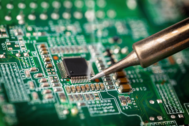
A brief overview of the presentation is provided to include the following visual representations: Tinning the Iron Tip, Through-Hole Soldering, Surface Mounted Soldering (SMT), Drag Soldering, and Rework and Repairs. Each technique label points out a summary of the main points of the technique. The appearance of the design is informative, aesthetic, and easily understandable.
- Heating the Joint: First place the advice of the soldering just on the pad and then the component lead. Briefly heat the joint using a heat source for a few seconds for it to be heated up.
- Applying Solder: Move the solder into alignment with the lead and the solder pad instead of the soldering iron, and the solder will flow around the lead and pad. Make sure you are using only enough solder to work the corners of the joint nicely and keep the whole surface smooth and shiny.
- Removing the Iron: Thereafter, stabilize the flux and take the heat away, but keep the joint in balance. Ensure the solder has completely melted and bonded to the PCB’s components before proceeding.
Steps to Soldering a PCB
Here are the basic steps for soldering a printed circuit board (PCB):
- Prepare Your Tools and Workspace: Get ready your soldering gun, solder, flux and other tools. Make sure to clean and lighten up your work conditions.
- Heat the Soldering Iron: Hook up and turn the soldering iron on to the required heat temperature (about 350 °C for lead solder).
- Clean the Soldering Iron Tip: Damp the tip of the iron on a sponge and get rid of the solder and contaminants by wiping off the iron.
- Apply Flux: Heat up the flux on the PCB pads and the leads of the component by melting a small amount of them. They will improve solder flow and the adhesion of the solder.
- Position the Component: Get the electronic component on to the PCB, with the leads accordingly placed at the pads.
- Heat the Joint: Place the tip of the soldering iron right on the center of the pad and the lead, heating both of them to approximately the same degree.
- Apply Solder: Stick the solder on the joint while the iron is active. For the joining of wires with ferrous metals, let the solder and ferrous metals melt to form a good connection.
- Inspect and Clean: Inspect the solder joint, which needs to be glossy and apex-shaped. Clean the areа with isopropyl alcohol and remove residual flux from it.
- Repeat for Other Components: In addition, do the other parts as in the above procedure.
- Final Inspection and Testing: Check that all components are soldered together after completing the soldering and inspect them for bridges or weak joints. Then you will test the circuit for functionality.
How To Solder A Circuit Board
Here’s a step-by-step guide on how to solder a circuit board:
- Gather Your Tools and Materials:
- Soldering iron
- Solder (lead-free or tin-lead alloy)
- Flux (to clean and improve solder flow)
- Circuit board (PCB)
- Electronic components
- Safety glasses
- Ventilation or fume extractor
- Prepare Your Workspace
- Arrange lighting and ventilation because they play a focal role.
- Group all your tools and components together.
- The surface of the PCB is getting cleaned.
- Place Components
- Install the components on the printed circuit board according to the circuit’s schematic diagram.
- E.g. For through-hole components, feed the leads through the openings in the PCB.
- For surface-mount components, align them on the marked pads below.
- Secure Components
- Place the leads in the holes of the PCB surface by bending it slightly to fix it in that position.
- Employ adhesive tape or tiny welding bits to hold down the housing of surface-mount accessories.
- Apply Flux
- Simply take the brush or dab flux onto the pads and leads, which will flow and prevent oxidation of the solder at the same time.
- Heat the Joint
- solder joint is soldered by touching the tip of soldering iron to a junction where the component lead meets a PCB pad. Heat the pad and the lead in unison.
- Apply Solder
- Touch the solder to the heating joint, not directly to the iron, as the latter could cause massive damage. The lead should melt and dribble in and around the pad and solder joint, leading to a smooth, shiny connection.
- Remove the Iron
- Wait until the solder flows, then remove the heated iron, but don’t let the solder go anywhere. Ask the patient to avoid moving the area of the joint until it becomes cool.
- Inspect the Joint
- Verify for a correct solder joint, the surface of which should be smooth, shiny and, for sure, free of gaps or excess solder.
- Trim Excess Leads
- Trim, using solder wires cutters, excess lead of the through-hole components placed nearby from the point where the solder is done.
- Use isopropyl alcohol as a solvent and clean with a brush or cloth to eliminate any flux residues.
- When all the components are soldered, apply a test to the circuit to ensure that it works well.
Best Practices for Successful Soldering
- Practice: Just like a skill that takes quitea bit of practice, it is the repetition that matters. Begin with bigger things and then move on to smaller ones so you get a chance to prepare more thoroughly and practice.
- Inspection: Use a magnifying glass or microscope to inspect and confirm your soldering points. Find shiny, glistening joints without imperfections, either in solder beads or obvious gaps.
- Reflowing: If a joint does not appear to be satisfactory, remove the solder tip from the soldering iron and reheat it gently. If necessary, add some extra solder to attain the desired result.
- Avoid Overheating: Prolong and heat interaction is not favorable for the PCB soldering processes and its components. Use the required amount of heat to avoid wasting any amount of heat and energy.
Common Soldering Mistakes And How To Avoid Them
Here are some common soldering mistakes and how to avoid them:
- Cold Joints
- Cause: Soldering with poor heating electricity.
- Avoidance: The key is to make the soldering iron heated at the right soldering temperatures that both the component lead and the pad on the PCB are heated evenly before solder is applied.
- Overheating components:
- Cause: Getting effected with heat if process goes too long or hot.
- Avoidance: By way of using a soldering iron with variable melting temperature and for just as long as it takes to melt the solder directly and create a joint, one can accomplish that.
- Solder Bridges:
- Cause: Solder should be applied in the correct amount; avoid bridging adjacent pads or leads.
- Avoidance: Always make use of enough solder as well as a fine-tipped soldering iron for the finer and more precise works.
- Insufficient Solder:
- Cause: Failing to apply enough soldering projects, hence having poor or incomplete joints.
- Avoidance: Make sure the solder fully covers the copper pad and goes around the component lead hot one secure attachment.
- Poor Component Placement:
- Cause: Parts misalignment, loose soldering joints, poor joint soldering, or incomplete component soldering.
- Avoidance: Consider doing a test fit of the components to see if they are in place and are oriented accordingly before soldering. You may also add a little solder or adhesive to fix them when you’re unsure of their placement.
- Oxidized Tip:
- Cause: The soldering equipment is the most used equipment in the research and development phase of the product cycle.
- Avoidance: Now and again, a brass sponge or tin wool should be used to mops the whole tip, and then it should be soldered through a small quantity of solder.
- Using the Wrong Type of Solder:
- Cause: Through substandard solders, such as plumbing solder, instead of switching to rosin core. Write your name in a sentence that thoroughly describes yourself.
- Avoidance: Do not forget to apply rosin-core solder that is made for electronic devices.
- Not Using Flux:
- Cause: Not applying flopping flux can lead to weak solder, where the joints don’t fuse together well.
- Avoidance: Always use flux in the solder jointing region to increase solderability and improve reliability.
- Inadequate Cleaning:
- Cause: PCB-based flux residue or other kinds of pollutants remain on the board.
- Avoidance: After finishing soldering, clean the PCB with isopropyl alcohol to get rid of all the unwanted residue left on the board.
It is vital to become aware of the mistakes that are made quite often, do something to stop them from happening, and create electrical connections. In this situation, high-quality soldering will be ensured, as will reliable electronic connections.
Conclusion
Soldering PCBs, being a major art, holds great potency in the electronics industry around the globe. With basic underpinning knowledge, selecting accurate tools, and following proper styles, you can build good-quality solder joints that let your electronics projects be on par with the best of you. Remember to prioritize safety, cleanliness, and inspection as the top things to focus on in order to get the optimum output on metal surfaces. Happy soldering!

