Soldering is one of the most important skills in electronics – allowing you to solder aluminum together robust and lasting junctions through components. Whether you’re an amateur or a master at it, getting a straight soldering joint is the goal of any project. In the course of this guide, we are going to present what different types of soldering joints you could use, what kind of tools you are going to need for silver soldering and also provide you with step-by-step instructions in order to complete soldering on your own with efficiency.
What is soldering?
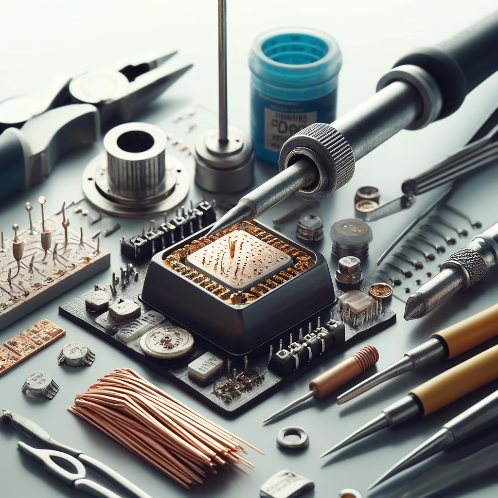
The soldering iron can be depicted melting the solder onto a joint between two metal components, the break down of the solder and the formation of a strong connection as a result will be shown. The Soldering Iron can be seen clearly beforehand that the solder is depicted as flowing following the shape of the joint.
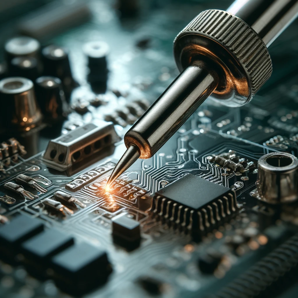
Soldering is a process that is used for combining two or more molten metal items by melting and flowing a small amount of filler metal zinc (solder) into the joint. The weld filler metal melts at a low temperature than the surrounding metal solder alloys. Soldering be a trendy technique in circuit assembly to attach parts to each other and insure electric conduction and mechanical strength. Acid core solder is used in other disciplines; we don’t use it for electronics work, so stay away from that type of solder.
Types of Soldering Joints
There are several types of soldering joints commonly used in electronics and other applications:
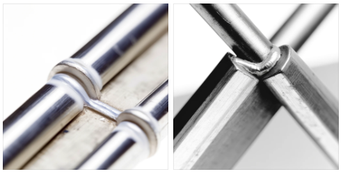
Lap Joint
Having the metal pieces going on top of each other and with solder applying to where they overlap in the picture below shows a typical Lap Joint in soldering.
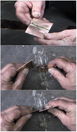
Two pieces of metal overlap, the metal pieces are placed one after another. The flowing solder is evened out on the overlap area. This type of joint is the most common utilizable in electronics, such as wiring or attaching components to a circuit boards.
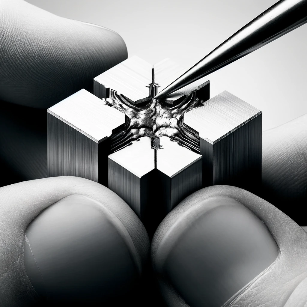
Butt Joint
The above is an exhibit of soldered Butt Joint creation in clear construction form with a clear illustration of two pieces of metal which are placed end to end and soldered joint.
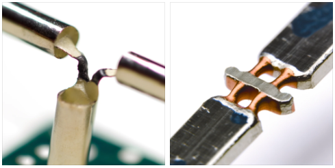
The first steps would entail putting the two-metal ends next to each other, and soldering them together. Apart from the breadboard, the Solder-less Joint is the most popular type used in electronics. It is mostly associated with attaching copper wire ends.
T-Joint
Here is the T-Joint in soldering for your reference. This is when we have one component perpendicular to another, like they’re forming a ‘T’ shape with the other.
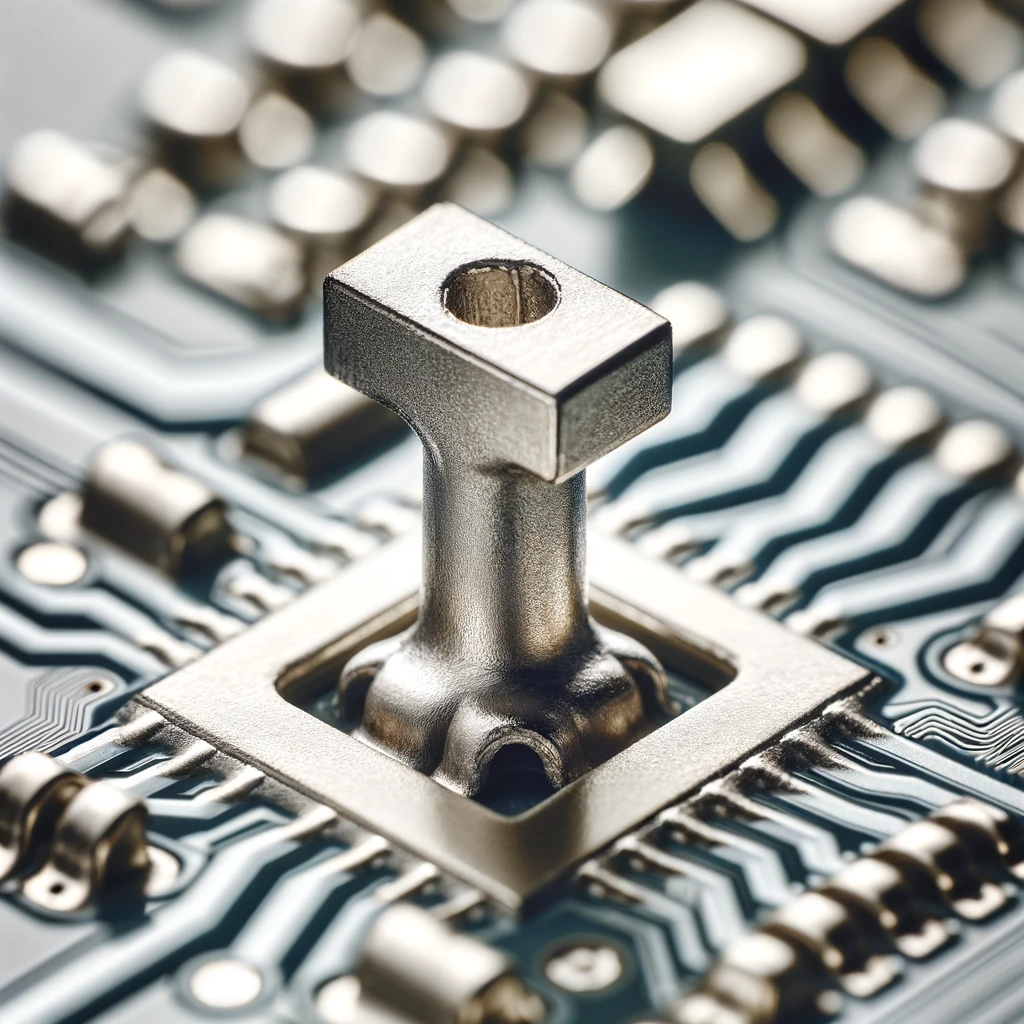
The solder is soldered in the direction parallel to the other which results in the formation of the ‘T’ shape. It is a motto joint frequently used in posts constructing angles and attaching components.
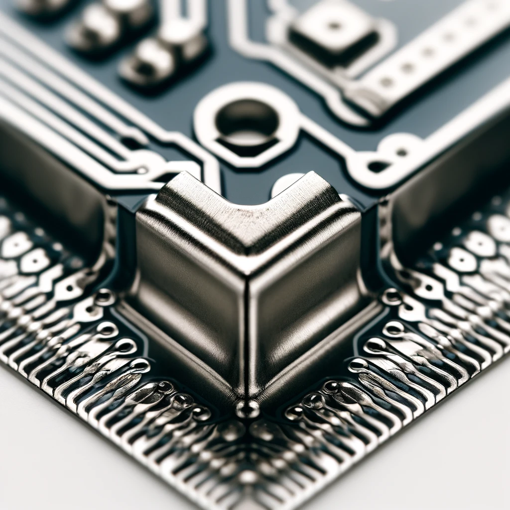
Corner Joint
Here is a clarifying example of Soldering Corner Joint, where two components meet at a 45-degree angle point, and make a corner. Solder is applied at the joint.
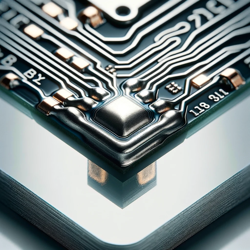
Like the T-joint where both parts are 45 degrees connecting simultaneously to from a corner. It less frequently done when we need to process electronics but sometimes we can use it in structural engineering.
Corner Joint
And here is the drawing illustration of Soldering Filleted Lap Joint showing the joint through two overlapping pieces of metal which are then soldered together to make the fillet strong.
A type of a lap joint where more silver solder is added and formed into a fillet in order to offer another strength factor.
Scarfed Joint
See here a clear construction lesson about the Soldered Scarf with visual aid present, showing how two beveled pieces of metal join to form an overlap that is to be joined with a heating element device referred to as soldering.
Across modes, these may be called Lap Joints but it also contains beveled edges of overlaps to generate an extensive surface for soldering.
Offset Joint
An Offset Joint of the soldering process depicted with two parallel pieces with one end of each piece offset another and both ends of these pieces soldered together is given below.
Two components are done with parallel connection while both ends of both components are soldered. This is employed when the straight cut joint is not possible due to insufficient space for a lap.
Each type of soldering joint is destined for a specific place in the construction and the features of the project that are relevant to the soldering will determine whether it is weak enough, strong enough, good enough electrically facilitating the work or enough room to place.
What are the functions of a solder joint?
The functions of a solder joint include:
- Electrical Connectivity: An electric current flows from one component to another and from one wire to another through a solder joint. The solder joint is kind of a bridge between the electrical components and wires.
- Mechanical Stability: Solder joints provide mechanical support by soldering the parts together and thereby providing the necessary support to maintain the components bed solid and free from any form of movement.
- Thermal Conductivity: Good solder joints make more heat from electronic components flow off as a heat transfer medium that is effective in thermal management.
- Corrosion Resistance: Solder is made with element that resists oxidation and corrosion which in turn guarantees the complete integrity of the joint and hence its longevity.
- Ease of Repair: Solder joints can be removed and replaced quickly as well as modified with no soldering skills only with a heating source. Through this process, solder joints can be reworked or repaired providing convenience for maintenance.
- Cost-Effectiveness: The fact that soldering is one of the most cost-effective ways of making strong and reliable connections facilitating such processes as welding which are quite expensive is an undeniable fact.
What is a good solder joint?
A good bond solder joint is characterized by the following:
- Shiny and Smooth: The solder appearance should be shiny and smooth enough to show that there was no problem melting or melt solder and flowing of solder.
- Proper Wetting: The solder should become molten and on the joining of the surfaces of components without voids, gaps and cracks should remain.
- Concave Fillet: The solder should form a rather rounded shape without peaks and valleys, surrounding the joint with a concave fillet that smoothly connects the two components.
- No Cold Joints: A soldering joint which does not appear bright and shiny (like the grainy surface similar to a cold solder joints due to inadequate enough heat) should always be considered as a defective joint.
- No Bridges or Shorts: The connecting (bridging) devices of one adjoining component with another joint or components should not cause shorts by accident.
- Mechanically Stable: The joint must be strong enough as to be isolated from the normal handling and vibrations indicating which it does not break down.
- No Flux Residue: Flux should be completely removed in case it was aggressive, otherwise any damage might occur, to the joint under repairs.
- No Solder Balls: A good solder joint should not have a bundle of small balls around them. The situation may indicate solder defects caused by root components of poor soldering practices or contamination.
The final solder joint must have the appropriate level of visual, mechanical and electrical integrity by its overall attributes.
Tools and Materials
To achieve good soldering results, you will need the following tools and materials:
- Soldering Iron: A tool that heats up to keep silver solder in a state that allows it to flow and fill up the joint, securing the components together.
- Solder: Composite of two or more metals that are sown together to make metal workpieces to metal alloy. It is characterized by the fact that it liquefies at a lower degree than the parts themselves.
- Flux: This chemical cleaning agent employed for the purpose of inhibiting the oxidation, which in itself takes place during the soldering process, takes place to have a good connection between the Solder and work pieces.
- Soldering Stand: A holder that supports the iron soldering gun and faces down when not in use would be used as to avoid the soldered hot surface to touch the workbench.
- Cleaning Sponge or Brass Wool: Functional more than a flamer to clean the soldering tip of the soldering iron, plus make elimination of oxidation and excess solder.
- Wire Strippers: Tools used to remove the protective layers off the cables by means of exposing the conductive metal. One of the most common types of injury is electrical shock that occurs due to contact with high-voltage power lines.
- Wire Cutters: Utilize equipment with scissors or other instruments to complete this job.
- Heat Sink: A clip or tool that minimizes extra heat exposure in sensitive components, possible for soldering damage.
- Safety Glasses: Safety eyewear to ensure your eyes from against pitfall of molten solder or flux spray.
- Ventilation or Fume Extractor: Equipment such as fans and fume hoods which are used to remove or filter eh fumes resulted from the soldering.
To have the right tools and materials on hand will be the key for you to get a successful and safe wave soldering process at home.
Common Ways to Make Solder Joints
Here are some common methods for making solder joints:
- Soldering Iron Method: The most popular approach, is where a soldering iron, heat up the electric current is transferred to the circuit board, where solder around connection points of components of a circuit board is melted.
- Reflow Soldering: The solder paste application is wide spread in surface mount technology (SMT) where the paste is first deposited on the board, components placed, and the whole assembly is heated in a reflow oven to fuse the solder.
- Wave Soldering: Application of the back-and-forth movement of one side of the molten solder oxide, features the coming off metal areas and giving rise to solder joints.
- Hot-Air Soldering: Hot a breath to solder the existing parts, especially when reworking boards is more helpful where earlier soldering defects will be remedied.
- Induction Soldering: Utilizes the creation of heat directly in the metal parts by the electromagnetic induction that occurs inside the assembly and as a result does not require an additional heat source.
These specific processes are applicable in different situations depending on the kind of a joint it is, which joints selected, providing strength or electrical conductivity. In addition to types of clothes, the design and the space too should be considered.
Steps to Soldering Perfect Joints
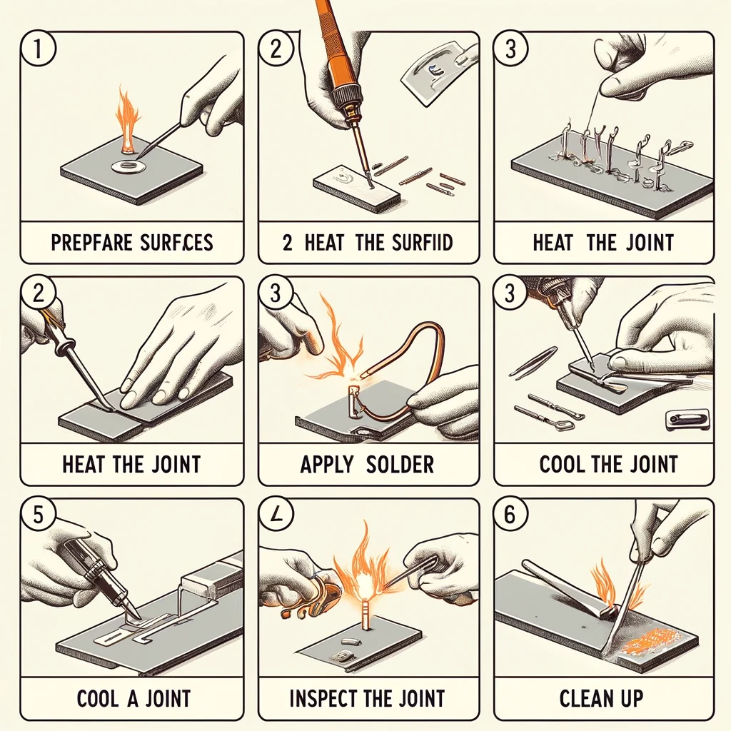
The following is a guide describing in detail, and in an orderly fashion, how to create perfect soldering joints. Each step is shown with a labeled diagram. Stages of the procedure are: prepping the surfaces, heating the joint, melting solder over joint, cooling the joint, inspecting the joint, and cleaning up.
To solder perfect joints, follow these steps:
- Prepare the Surfaces: Scrub the sanded surfaces with wet laundry clothing. The cooking utensils and food containers have to be clean to prevent blemishes and grime.
- Heat the Joint: Try placing tip of soldering iron to the meeing point of two components. Heat joint for about a few seconds to make it where it can be when it is needed.
- Apply Solder: Hook the solder on a joint and not the tip of the iron. Heat from the joint should melt the solder, and it will subsequently flow into and around the joint by two-way pouring process.
- Cool the Joint: Stop the heating and let the joint cool down without any external factor. After demolding do not move the joint while it is still cooling to avoid giving a loose connection.
- Inspect the Joint: The solder joint should shine out and be beautifully, clearly solder around the fillet with the solder. If your joint appears rough, lumpy, or even cracked, you need to rescolder it.
- Clean Up: This step involves wiping off flux with an isopropyl alcohol-soaked fabric after forming the joint.
Tips for Success
- Practice: Mistakes are inevitable when soldering, which means you will need to practice time and again as you perfect your skills. Explore the building of joints first and work through the increasingly difficult ones.
- Maintain Your Iron: Keep the end of your soldering iron meticulously clean and frequently re-tinned for the best output.
- Use the Right Temperature: It is too hot and you may burn out components. Solder won’t flow properly does at a lower temperatures. Load the right amount of material that you are using, as fitting.
- Safety First: Ensure that you work with an amply ventilated stuff and wear safety goggles to prevent splashes from your eyes.
Follow these efficient formulations and your soldering joint perfectness would be guaranteed by the end of all your electronic construction.
Common Lead-Free Solder Joint Defects
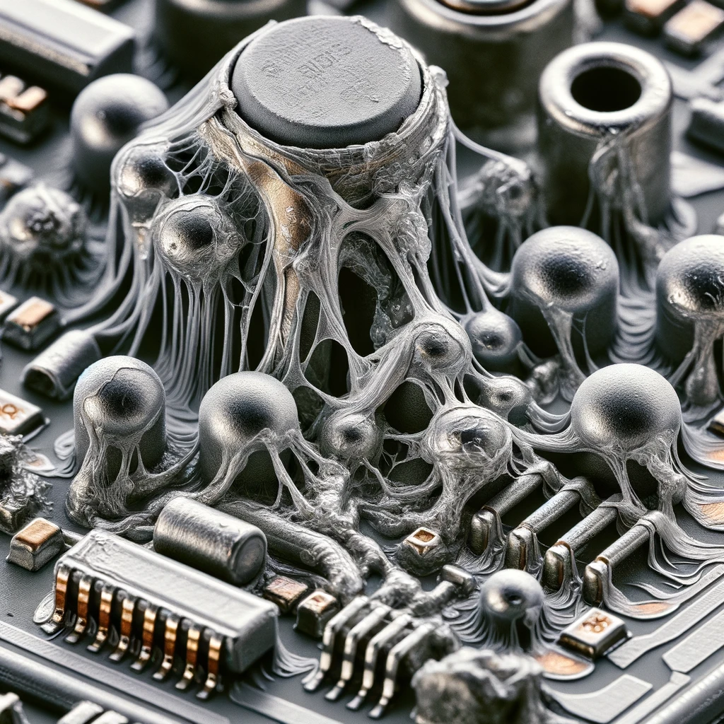
Common lead-free solder joint defects include:
- Cold Joint: A soldering joint which looked either shiny and smooth, an uneven graininess, or a boutting texture, indicating that the solder has not melt properly. Response might be obtained due to low or inefficient wetting.
- Bridging: An unexpected connection that can happen either between adjacent pads or leads, which will cause shorts in the volume.
- Voiding: The filling of the void/air cavities or pockets of solder which lessens the bond between the joint and may drastically diminish the heat and the electrical conductivity of the joint.
- Tombstoning: A situation when the surface mount part gets partially lifted off from the PCB during the reflow cycle and only one of the ends gets soldered but the other remains unattached on the board.
- Solder Balling: The creation of small solder balls that can be pulled out of the joint when over-soldered, or may appear as a result of solder splattering during reflow soldering or contamination.
- Non-Wetting: Unsoldering happens when the solder does not well manually adhere to the component surface the surface of the pad the PCB, hence forming the weak or no joint.
- Excessive Intermetallic Compound (IMC) Growth: Excessive formation of Inter Metalic Compounds (IMCs) at the interface of the solder and the substrate can give rise to a brittle soldering which has tendency to fail.
- Cracking: Poor solder quality may lead to cracks in the soldering joints as a result of thermal cycles, mechanical stress, or the presence of impurities.
- Graping: The formation of disordered consolidation particles of solder paste which gives the joint a rough, grainy surface.
- Head-in-Pillow (HiP): Failures occurs when a BGA (Ball Grid Array) solder ball does not fit well and coalesce nicely with the pad on the board resembling a head resting on a pillow
Correction of these flaws includes among other things, the application of suitable materials, the use agreed soldering method and observance of given thermal profile.
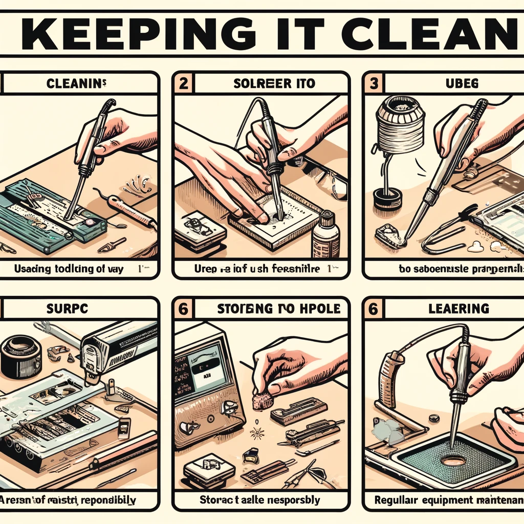
Keeping it clean
The photo symbolizes all these best practices that includes the soldering iron tip cleaning, careful using of flux, keep the work area and tools clean, store your tools properly, dispose your waste as prescribed, and maintain the equipment regularly. The motion of the avatar is labeled easily with the unambiguous names shown in a visual way, pointing on the action that is exactly performed.
The only of the your soldering station and equipment is that it can have a very big effect on getting good solder connections and last through many years the quality of your tools. Here are some tips for keeping your soldering area clean:
- Clean the Soldering Iron Tip: Make use of a moist sponge or brass wool to sweep the head of the soldering iron after every use. This will get rid of the oxidation and solder overflow, securing the surface for future joint.
- Use Flux Wisely: Do not proceed with the application of flux about the unwanted residue. Separation of flux can trigger rust, so it is wise to keep off the PCB and components from soldering flux after soldering.
- Maintain a Clean Work Surface: Ensure to keep the soldering station gets rid of clutter and dirt. Use special surface or mat with heat resistance to avoid accidents on the work area.
- Store Tools Properly: Always store your soldering iron in its stand when the welding is completed. Don’t leave other tools and welding equipment out in the open. This feature allows one to avoid unintentional damage and contamination.
- Dispose of Waste Responsibly: Accumulate and eliminate solder scraps, languishing flux, and other waste in the form of compliance with local regulations. Use our AI to write for you about the destructive erosion of solitary confinement on the mental health of inmates.
- Regular Equipment Maintenance: From time to time, after you have inspected your soldering equipment, clean the iron, work stand, and ventilation system.
Time to solder
When it’s time to solder, make sure you have all your tools and materials ready, and follow these steps for a successful soldering experience:
- Set Up Your Workspace: This should be an isolated, properly ventilated and well-isolated zone to ensure safety. This space should not be able to retain heat. Time to switch on the soldering iron and make it hot to get to the right higher temperatures.
- Prepare the Components: Sand or brush the areas which are to be soldered with the #180 sandpaper or a wire brush. If you’re soldering wires and you hadn’t removed the insulation from the ends, do it now, and twist the strands together before you begin.
- Apply Flux: If need be, coat both surfaces with a pinch of flux inside so that the solder can flow properly. This will eliminate the bubbles and oxide formation during soldering that hamper the quality of work.
- Tin the Soldering Iron Tip: Align a little piece of the solder against the iron tip. With this electrode being more thermal conductive, the heat transfer from the iron to the components will greatly improve.
- Heat the Joint: place the end of the soldering iron in the hole so that it will make both parts of the joint hot at the same time. Halt the heating process for some duration to equalize the heat.
- Apply Solder: Solder again to the joint, but not directly to the hot end of the iron. The heat is transmitted from these components to the solder, which will then run into the joint when it melts.
- Remove the Heat: Lastly, place the soldering iron end and leave the solder covering the joint for some time before you let it cool naturally.
- Inspect the Joint: See if the solder joint is bright and flawless, there is a satisfactory connection between the located components.
- Clean Up: Take isopropyl alcohol and wipe with no residue of flux from the joint after removing.
Don’t forget about working in a well-ventilated area and always put safety goggles on to prevent any contact with spectral. Happy soldering!
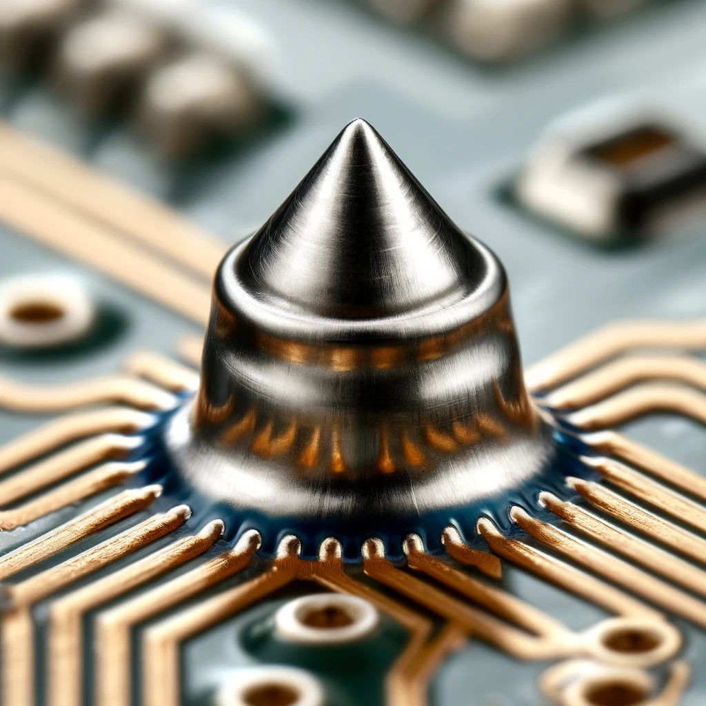
Should You Use Thermal Reliefs to Enhance PCB Solder Joint Strength?
The welding of surface mounts to large copper places or ground planes can be much extended by using the thermal reliefs of the motherboard. Thermal reliefs are created so that the heat will remain localized on the pad and then be dissipated from the pad to the surrounding copper pipe, pipe soldering, steel pipe which facilitates the process of heating the pad up to the desired soldering temperature or too much heat. This can result in a better solder joint because:
- Improved Heat Control: Thermal relief is placed under the heaters so as to confine the heat to a small area, and the larger copper area does not get warmed too fast due to this. It does that by enabling the faster transfer of heat to the solder joint. Then, once the solder melts and flows in the proper way, it can easily make a strong connection.
- Reduced Risk of Cold Joints: It heats up more efficiently, and hence, with a lower risk of the formation of a cold solder joint, which means that the solder doesn’t melt down completely due to unavailability of sufficient heat.
- Easier Rework: There is a provision of thermal reliefs such that a connector can be detached or re-soldered which make it convenient for the joint switch to be heated again without damaging the nearby section.
- Better Mechanical Strength: The solder joint connectivity is assured by applying thermal reliefs in this process, which adds to its mechanical strength too.
Nevertheless, while doing the paring, it should always be done thoughtfully. There is also the fact that the thermal reliefs can create fairly good electrical resistance. they operate mainly in cases, where heat dissipation matters during soldering tools of the pads connected to large copper areas of the motherboard or other common components like the power or ground planes. Ultrasonic here the liquid solder behaves like an ultrasonic cleaner, destroying the oxide layer. This is where checking PCB design tie lines guidelines and reflecting specific circuit details, such as the use of thermal reliefs, comes into play.
Characteristics of a good solder joint
A good solder joint has several key characteristics that indicate it has been formed properly and will provide reliable electrical and mechanical connections:
- Shiny and Smooth Surface: Assures excellent joint formation and good wetting of the solder.
- Proper Wetting: Meets adhesion and conductivity requirements.
- Concave Fillet Shape: Indicates well-organization, fit, and grip between the parts, unlike the claw hammer.
- No Excess Solder: Avoids short-circuits and sustains flexibility. Listen to the given audio and follow the instructions:
- No Solder Bridges: Creates a distance between two joints thus, no one should be connected accidentally.
- No Voids or Bubbles: Diminish the risk of poor joints conduction, and maintain the original excellent property of biometal.
- Correct Amount of Flux: Generates a perfect melting or soldering without emitting dangerous substances.
- Mechanical Strength: Resist the mechanical stress without getting cracked.
- Clean Appearance: No oxidation, corrosion, and excessive flux residue left for the safety and reliability of the joints in a long-term working environment.
What makes a bad solder joint?
A bad solder joint can result from several factors, and it typically exhibits one or more of the following characteristics:
- Dull or Grainy Appearance: Shows failure due to cold joint, since the solder cubs did not soften and merge well into the copper.
- Poor Wetting: The solder does not flow out clean straight lines which is may be the reason of poor adhesion.
- Excess Solder: Joints may be wrong if too much solder will lead free solder formulations to the formation of bridges between neighboring joints or will reduce flexibility.
- Solder Bridges: Unforeseen cracks or joints between the neighboring pads may allow the discharge of current.
- Voids or Bubbles: There are air pockets trapped within the solder and these are the points of high resistance which weaken the joint.
- Insufficient Flux: Flux absence can cause bad deposition and evaporation.
- Weak Mechanical Strength: Joint has a smaller cross-section, which makes it to break or deform when subjected to load (stress).
- Dirty or Corroded: The presence of oxidation, corrosion, flux, or residue can lead to unexpected deviations in the performance.
- Overheated Components: High temperatures can cause oxidation of conductors and failures within circuit board.
A faulty solder contact can compromise the quality and remissibility of electronic circuits in question, which cause intermittent or high resistance connections or complete device failure.
What happens when you have cold-soldered joints?
Sometimes that cold-soldered joints happen and the solder doesn’t melt thoroughly enough so that electrical connection is not as strong and reliable as it should. Such joints are usually unexciting and malblended, giving a low lustrous finish instead of a well soldered joint. The process can be prone to patchy connections, higher electrical resistance, and ultimately short circuit failures when the soldering does not form a good bond with the component leads or the circuit boards. After the cold-soldered joints break down, reheat them using a soldering iron until they melt and fill the whole joint creating a good bonding.
Conclusion
Finally, its sound bracing gives the guitar a resonant and elaborate tone. As you develop your soldering skills, you need to demonstrate a good understanding of the different types of soldering joints, their function and how to make them properly. A well-done project will require you to comply with these three requirements effectively. By the compliance with proper soldering rules, for example through accurate tools and materials utilization, proper joint techniques, and cleanliness maintenance, you can obtain strong and reliable solder joints. Additionally, being inquisitive of mostly typical solder joint defects as well as methods to overcome them is no less important to produce the quality products and some electrically conductive. Happy soldering!